Basic HTML Version


www.geotechnicalnews.com
Geotechnical News • December 2012
53
(e), is the sum of specific yield and
specific retention (Table 3).
n =
Y
s
+ R
s
(5)
e =
n/(1-n)
(6)
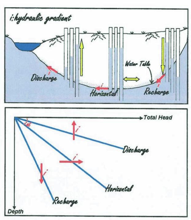
In a watershed, depending on the
topographic and hydraulic gradient
conditions, areas or zones of recharge
and recharge can exist with the ground
water flow downwardly and upwardly
respectively; or otherwise horizontally
(Figure 2).
Other ground water flow form by non-
body forces are matric or capillary
flow in unsaturated soils (Ф
m
), osmatic
or diffusion (Ф
s
) (versus advection
where driving force is the body force
or primarily gravitational force (Ф
g
)),
and coupled flows where the driving
force is due to a temperature or chemi-
cal concentration gradient in addition
to other driving forces noted above.
In contaminant hydrogeology, it is
important to note that through a 1.0 m
thick clay soil barrier with a hydraulic
conductivity (K-value) of 10
-8
cm/s,
the advective flow takes about 100
years, whereas the diffusive flow takes
only about 5 years! [4].
The equations for flow of ground
water under gravitational body forces,
which is usually the case for dewater-
ing or drainage systems, consist of
condition, motion and solution equa-
tions.
The condition equations determine
boundary conditions by a conceptual
site model, hydraulic conductivity
K-values of soil strata and flow type
(steady or transient, uniform or varied,
laminar or turbulent).
The motion equations consist of mass
conservation (water budget analysis
for example), energy conservation
(Bernouli equation) and Darcy’s law.
The solution equations may con-
sist of analytical (simplified two-
dimensional), pictorial (flow nets) and
numerical (ground water modeling)
solutions.
The above-noted equations are utilized
to assess the water quantity and qual-
ity, potential aquatic and terrestrial
adverse effects, and the monitoring
program and contingency/mitiga-
tive measures commensurate to the
proposed development construction
dewatering and post-construction
drainage needs in compliance with the
water-taking regulatory requirements.
For a water-taking quantity assess-
ment, both the “source” and the “sink”
should be characterized. The source
can be either ground water or surface
water or a combination of both. The
sink can be an existing natural feature
of the site and surrounding hydrogeo-
logic setting, a construction dewater-
ing scheme that may include well
points and eductor wells, or a post-
construction drainage facility.
For a water-taking quantity risk
assessment, the construction dewater-
ing or post-construction drainage dis-
charge rate and zone-of-influence and/
Table 3. Typical Soil-Water System Parameters
Soil Type
Gravel
Sand
Silt
Clay
Y
s
(%)
23
30
18
3
R
s
(%)
9
12
29
47
n (%)
32
42
47
50
e
0.47
0.72
0.89
1.00
Figure 2. Vertical and horizontal ground water flow gradients.