Basic HTML Version


www.geotechnicalnews.com
Geotechnical News • December 2012
55
concrete caisson shoring has particu-
larly the following advantages:
i. The wall relative impermeabil-
ity will minimize and facilitate the
construction dewatering rate inside
the shored area of excavation.
ii. The dewatering zone-of-influence
and potential impacts in the vicin-
ity, such as ground subsidence or
settlement of the structures and
migration of contaminant plume, if
any, will be reduced.
The scope and cost of a permanent
(post-construction) drainage system
required, in addition to the above-
noted factors except shoring, depend
very much on drainage aggregate,
wrapping filter fabric, perforated
subdrain pipes, header solid pipes and
pumping the collected ground water to
a discharge receiving facility.
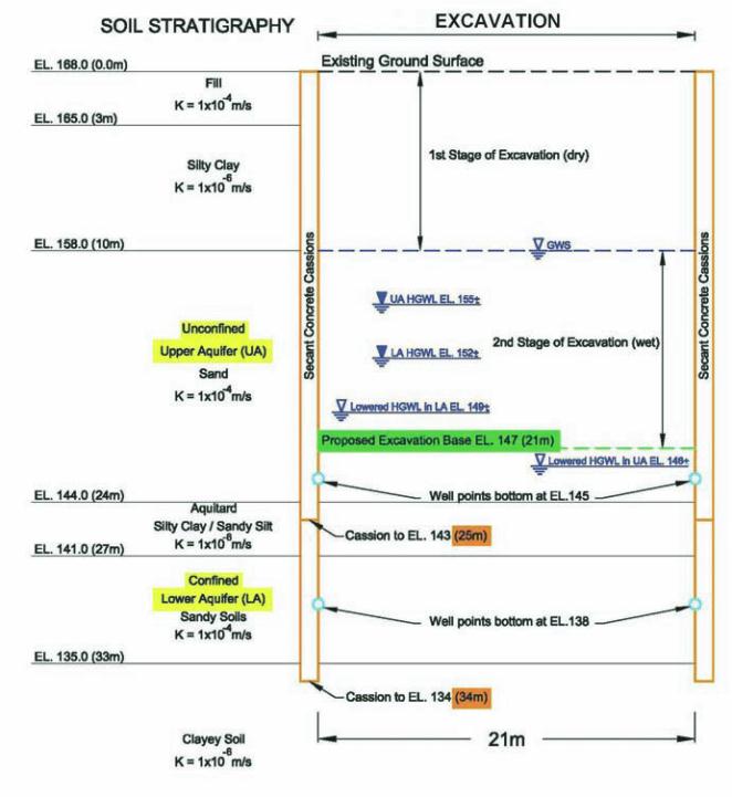
A typical hydrogeological and dewa-
tering conceptual model is depicted on
Figure 3 for a caisson-walled shoring
system with two optional depths of 25
and 35 m in relation to the soil stratig-
raphy and upper and lower aquifer and
aquitard conditions.
Estimation of dewatering
discharge rate and zone-of-
influence
Based on the hydrogeological and
geotechnical factors described above,
the dewatering and drainage require-
ments primarily depend on:
i. Hydrostatic ground water level;
ii. The ground water level lowering re-
quired for dry working conditions
during construction and stability of
the shoring augered holes bottom,
excavation base and underside of
the footings; and
iii. Soil stratigraphy and aquifer hy-
draulic conductivity K-value and
hydraulic gradients.
The estimation of the construction
(temporary) dewatering and post-
construction (permanent) drainage
discharge rates, construction duration
and the water-taking zone-of-influence
for assessment of adverse effects
are the important data for the PTTW
application.
The dewatering discharge rate can
be estimated by one of the following
methods depending on the soil stra-
tigraphy, ground water and boundary
conditions such as the confinement
created by a shoring system:
i. Application of the Darcy’s equation:
Q = KiA, where K is hydraulic con-
ductivity, i is hydraulic gradient of
dewatering flow for lowering the
hydrostatic ground water level to a
desired level and A is seepage area
in the excavation, for a simplified
two dimensional model within the
dewatering zone-of-influence. An-
other method of calculating Q of
this simplified category would be
by constructing deliberately a flow
net of the dewatering model;
ii. Simple volumetric calculation of
the aquifer drainable water content
where the aquifer is confined by a
rather impervious shoring system
such as secant concrete caissons
and underlying rather impervious
clayey soils;
iii.Application of Forchheimer’s for-
mula to dewatered excavation as a
large circular (or equivalent) well
(Suzuki and Yokoya, March 1992);
or
iv. Numerical ground water modelling
by using a finite-element software.
The zone-of-influence (R
o
) for the
required ground water level lowering
or drawdown (D
d
) can be estimated by
one of the following methods:
Figure 3. Typical hydrogeological and dewatering conceptual model.