Basic HTML Version


www.geotechnicalnews.com
Geotechnical News • March 2013
25
GEOTECHNICAL INSTRUMENTATION NEWS
itoring programs. Practical constraints
include short schedules, limited bud-
gets, no easy access to areas, damage
to equipment or instrumentation, lack
of understanding of roles and respon-
sibilities, unexpected changes, and
conflicting priorities/goals/experience
amongst project stakeholders.
In such cases we need to evaluate the
situation and adapt the monitoring
program in order to achieve its objec-
tive of providing vital information. We
have to remember that the monitoring
data is of importance for monitor-
ing the performance of a design or
structure, to verify assumptions and
mitigate risk, as well as the safety of
all those involved in the construction.
Challenge 1 – Unforeseen piling
details
At a high-rise condominium project
in downtown Toronto, the monitoring
plan included inclinometer casings
attached to piles, and targets on the
piles for monitoring movement of the
shoring wall. These reflective targets
are typically placed at the top of each
pile for monitoring of horizontal and
vertical movement of the shoring and
are surveyed with an accuracy of ±
2mm. A typical site can have 100 to
300 piles. While there is expected
movement of the wall, neighbour-
ing buildings and structures are not
expected to experience movement.
The plan also included precision tar-
gets using prisms or reflective targets
that are placed on the structures, usu-
ally along the perimeter of the walls
and in far fewer numbers than the
targets on the piles, and are surveyed
with an accuracy of ± 1mm. In addi-
tion, five extensometers were installed
in sensitive areas to measure horizon-
tal wall movements and an array of
electrolevels was placed along joints
in the adjacent underground subway
transit to monitor horizontal and verti-
cal differential movements between
tunnel segments.
Our typical installation detail for
monitoring of shoring excavations
involves attaching the inclinometer
casings to the piles. The inclinometers
were to be installed in eight locations
and ranged from approximately 76
to 110 feet in length. However, due
to their extreme depths, the piles for
the shoring wall were not the typi-
cal wide flange I-beams used in local
construction. Instead, two of the wide
flange beams were welded together
along their length and a pipe pile was
welded to the bottom to extend the
overall lengths. Due to space, budget
and schedule constraints switching to
drilled inclinometers was not practi-
cable, and we needed to work with the
shoring contractor to achieve an atypi-
cal method of attaching the inclinom-
eter casings.
An installation method was devised to
run the casing along the outside of the
double pile at the upper end. A long
notch was cut out of the middle of the
pile nearing the transition to the pipe
pile at the bottom. The inclinometer
would be slightly curved to run down
into the notch and into the centre of
the pipe pile below, shown in Figure 1.
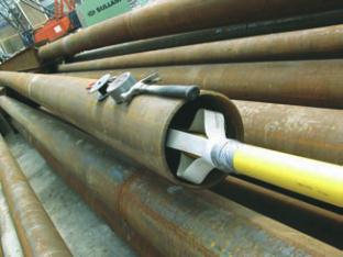
To avoid excessive movement in the
pipe pile section that would affect
readings, centralizers were positioned
along the length of the casing as seen
in Figure 2. Figure 3 shows a custom-
made base, consisting of a metal tube
(which would contain the bottom of
the inclinometer casing) welded to a
flat plate, which was in turn welded to
the edge of the bottom of the pipe pile
to prevent any downward movement
of the inclinometer casing.
With the successful installation of
the inclinometer casing, readings
proceeded as the shoring wall was
installed and excavation progressed.
Challenge 2 – Damage to
inclinometer casing
A problem arose when during the
installation of a tieback, the drill rig
hit an installed inclinometer cas-
ing. Fortunately, the site personnel
contacted our staff to notify us of the
situation. If the tieback installation
had continued, the inclinometer casing
would have been filled with grout.
To salvage the inclinometer and the
vital information it provided, staff
developed a plan to thread a smaller
diameter casing into the damaged
casing. The annulus between the larger
and smaller casing was grouted to
prevent movement and anomalous
readings. This remedy was success-
ful and inclinometer readings were
continued.
Lessons Learned
In this brief case history, the instal-
lation of the inclinometer casing was
atypical and the execution was a
challenge. There was also unforeseen
damage to one of the inclinometer cas-
Figure 1. Lower section of pile with
inclinometer casing transition to
pipe pile.
Figure 2. Centralizers in pipe pile
section.