Basic HTML Version


30
Geotechnical News • March 2013
www.geotechnicalnews.com
THE GROUT LINE
largest in the United States. Immedi-
ately downstream of the dam is a trout
hatchery operated by the US Fish and
Wildlife Service.
Two grout lines were required by the
contract. The first grout line was in the
gallery tunnel near the base of the con-
crete gravity structure. A second grout
line was along the downstream toe
near the contact between the concrete
and earth fill adjacent to the switch-
yard associated with the hydroelectric
powerhouse. Both grout lines paral-
leled grout lines placed in the 1940s
(gallery) and 1968-1975 (downstream
toe). The designers decided that it
would be beneficial to be able to dif-
ferentiate between the modern grouts
and historical grouts by color, and thus
required dyed grout. In addition, it
was thought that dyed grout would be
easier to notice if grout found its way
into the trout hatchery intake, which
was located as close as 50-feet to the
downstream toe grout line. Figure 1
shows the location of the grout lines,
along with the trout hatchery.
Methods
A wet dye injection system was
utilized for the injection of dye at
Wolf Creek. Dye was provided by the
supplier wet and injected wet. Col-
loidal grout mixers were utilized by
the contractor to mix the grout, and
the dye was mixed with the grout in
the colloidal mixer. The ASTM C
979-compliant dye chosen by Judy
Company was sourced from Solomon
Colors, and yellow was the color cho-
sen. The dye was mixed at 2.5-percent
by weight of cementitious material
(Portland cement plus fly ash).
Wasted grout is a fact of life on
production grouting jobs, and dyed
grout could complicate disposal. Grout
that is not injected into grout holes
is typically wasted; this includes the
quantity used to fill the grout lines.
Once hardened, the dye is trapped
in the grout. However, in the liquid
state or semi-solid state, when mixed
with water, there is the probability
that the water-soluble dye could enter
the waste water stream. Dyed water
is pretty obvious when entering a
watercourse.
A temporary waste water treatment
plant was established at the beginning
of the job to treat drilling fluids, rain-
water, water from gallery drains, waste
grout and other associated contract
waste waters. The Corps had concern
that some dyes may be very difficult to
remove from the waste-water stream,
and therefore did not specify the color
to be used. Discharge of dyed water
into the Cumberland River would be
negative from several standpoints. The
waste water treatment plant was able
to successfully remove all traces of
dye from the discharge water.
Effects of the dye on grout
There were rigorous grout testing
requirements on this contract. A suite
of six grout mixes was developed by
the contract to meet contract require-
ments, with water-to-cement ratios
ranging from 1.9 to 0.7. Grout mixes
were tested every four hours for
viscosity using a Marsh funnel and
density using a mud balance. Every
day, grout cubes were cast and later
tested for compressive strength at 7,
14, and 28 days. Bleed and pressure-
filtration tests were conducted weekly.
Initial set time and final set time tests
were conducted monthly. Testing
showed the dyed grout to consistently
be within specified limits.
One day, a batch of un-dyed grout
was mixed immediately before a dyed
grout batch; testing showed little dif-
ference in physical properties between
dyed and un-dyed grout. Compressive
strength testing was performed on
un-dyed and dyed grouts. The strength
differences were negligible. The same
batches were tested for Marsh Fun-
nel Viscosity, Mud Balance Density,
Bleed, Pressure Filtration, and Set
Time. None of these tests showed any
differences between the dyed and un-
dyed grout.
Results
The dyed grout worked as desired.
Figure 2 shows a photograph of hard-
Figure 2. Dyed and un-dyed Grout
Samples. Concentrations of dye (by
weight of cement) are 0-percent,
2.5-percent, 5-percent, and 7.5-per-
cent, as marked on the samples.
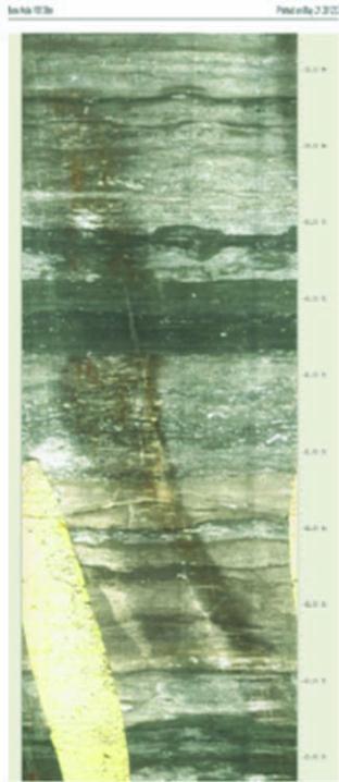
Figure 3. Dyed grout in an inter-
sected hole in a downhole camera
image. The image shows the entire
circumference of the hole. Noted
depth intervals are 6-inches on the
right side, interval for image is 58.76
ft to 63.65 ft.