Basic HTML Version


www.geotechnicalnews.com
Geotechnical News • March 2013
45
of subsurface failure and act as a
deeper rooted biotechnical composite.
However, there is a limitation for the
vegetated confinement system where
the flow velocity should be limited
from 2 to 3 m/s due to the tendency of
the nearly impermeable cells to sustain
scouring under high flow velocities.
Therefore, the confinement system
can be filled with concrete of gravel
to create a hard armor in high flow
conditions. Generally, a geotextile will
be placed beneath the confinement
system to provide separation and/or
filtration. For soil erosion control,
the confinement system can apply
at steep slope revegetation, channel
liners, shoreline revetment, retaining
walls, boat ramps and low flow stream
crossings.
History and background of soil
confinement system
Geosynthetics is a very diverse
and important group of construc-
tion materials during the past 35
years. They are produced from a
range of base polymers, most nota-
bly are polyester, poly ethylene and
polypropylene. These polymers are
characterized by high flexibility, low
weight, high strength and outstanding
durability. Geosynthetics products
has been designed and adapted to
meet a number of specific functions
such as filtration, drainage, separa-
tion, confinement, and the retention
and reinforcement of soil. The first
use of geosynthetics in major soil
stabilization projects is in the early
1970s when both woven and non-
woven geotextiles were used as key
component in road base stabilization
and erosion control projects. Now,
geosynthetic products include an
extensive range of woven and non-
woven geotextiles, geogrids, geomem-
branes, geonets and geocells. Geocell
confinement system was developed
from a co-operative development
effort between the Presto Products
Company and the US Army Corps of
Engineers. Geocells were originally
evolved to provide load support to
military vehicles traveling over soil of
low shear strength. Other applications
include soil retention in gravity and
geogrid reinforced retaining walls and
erosion protection in channel linings
and slope protection. The potential
value of geocell confinement system
in erosion control was first recognized
in the early 1980s. Today, the state
of the practice for geocell systems in
slope protection and channel lining
applications includes the use of Kevlar
tensile tendons to assist in distributing
the down slope driving forces to the
stable subgrade and pre-engineered
perforations to improve drainage and
infill material retention.
Installation of soil confinement
system
The installation of confinement system
may be little different, depends on the
product company. However, generally
the way of installation is mostly to be
the same. The installation of confine-
ment system on slopes is relatively
simple and even can be easily per-
formed by unskilled labours. The fol-
lowing procedures are based on Tenax
Tenweb Geocell:
1. Site preparation
• Clearing and grubbing the site
• Site should be graded as specified
by the designer
• The surface should be as smooth as
possible
2. Placement of the geocell panels
• Geocell panels will be expanded to
the full open dimension and par-
allel to the flow direction. Each
panel will be anchorage at the top
of the slope in a trench whose di-
mensions are determined by design
engineer. If it is possible, the an-
chorage trench at the top can be
filled with concrete (to reduce the
embedded length).
• Along the slope the geocells will
be anchored with pins. The spac-
ing between the pins will be deter-
mined by the design engineer. Pins
have shape and length depending
on the soil characteristics. Pin di-
ameter should be 8 mm minimum.
Each pin should be placed at the
junctions of the panel. Pins are
placed in stagger pattern so that
like the number 5 on a dice.
3. Junction between panels
• Adjacent panels should be fixed by
pins, one pin every 2-4 cells.
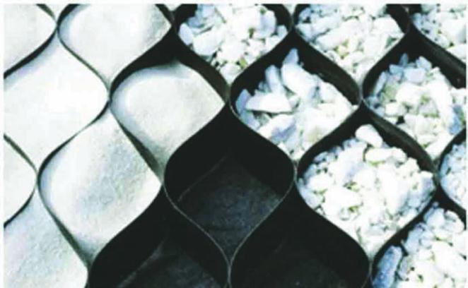
4. Infill the geocells
• Infill in the geocells is influenced
by hydraulics, soil conditions, and
aesthetics. The geocells can ac-
commodate infills and finishes
such as soil/grass, gravel. Infill
can be placed by the use of a front
Figure 2. Soil confinement system with the infill.