Basic HTML Version


28
Geotechnical News • June 2013
www.geotechnicalnews.com
GEOTECHNICAL INSTRUMENTATION NEWS
Field monitoring challenges, Episode 2
Unforeseen movements (depth and magnitude)
Marcelo Chuaqui and Wing Lam
Introduction
Continuing our series on Field Moni-
toring Challenges from the perspective
of a specialized monitoring contractor,
we present situations where we could
not execute a monitoring program as
planned or where unexpected chal-
lenges arose. Typically the constraints
consist of short schedules, limited
budgets, no easy access to areas, dam-
age to equipment or instrumentation,
lack of understanding of roles and
responsibilities, unexpected changes,
and conflicting priorities/goals/experi-
ence amongst project stakeholders.
In these instances, the situation has
to be evaluated and solutions must be
implemented to continue providing the
monitoring data. The data are valuable
for assessing the performance of a
design or structure, to verify assump-
tions and mitigate risk, as well as the
safety of all those involved in the
construction.
In describing these challenges, poten-
tial solutions and the results, we hope-
fully provide some lessons learned.
Challenge – Unforeseen Move-
ments (Depth and Magnitude)
In the Greater Toronto Area, a
roadway was being reconstructed
that included widening the road into
an adjacent wetland area in difficult
ground conditions that included soft
peat. The peat line was estimated
to extend approximately 13 metres
below grade at some points. The soft
and variable wetland soils would not
be able to provide adequate support
and lateral confinement for the road
and associated utilities. A permanent
retaining wall was to be put in place
to limit the potential road and under-
ground utility deformation.
Within the proposed widened por-
tion of the road, two sheet pile walls,
approximately 13 metres apart,
contained an area of 0.4 MPa filler
caissons that were part of a drilled
shaft peat removal plan. Within this
area, slightly offset from the sheet pile
walls, caisson walls would be installed
with 20 MPa concrete for king piles
and anchor piles and 2 MPa concrete
for primary and secondary fillers.
Anchor piles would contain double
wide flange I-beams. The two caisson
walls would be connected together
with tie-rods and tiebacks would
limit the wall movement. The length
of the proposed road widening was
approximately 110 metres. Sections of
the proposed widening are shown in
Figures 1 and 2.
The monitoring plan for the retaining
wall system included 15 inclinometers,
68 to 108 feet in length, both attached
to piles and borehole locations to mea-
sure below ground movements.
Twenty four deep monitoring points
were installed in two rows along the
length of the proposed road area to
measure ground settlement. These
were designed in order to be able to
add a section to the monitoring point
as fill material raised the grade. A base
plate was welded to a steel rod sec-
tion that was allowed to move freely
vertically and surrounded by steel
pipe sections. Centralizers kept the
steel rod section correctly positioned
as rods and pipe sections were added
using couplers. When readings were
required, the protective top cap was
removed and a specially machined bar
with a reflective target was coupled to
the internal steel rod.
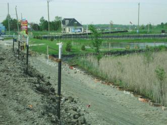
Figure 1. Section of proposed widened road showing wetlands.