Basic HTML Version


www.geotechnicalnews.com
Geotechnical News • March 2014
43
THE GROUT LINE
grout effort, and impose harm to the
tunnel surroundings as injecting grout
material into neighboring houses and
road/railway bases in the close vicinity
of the tunnel work. Today the typical
specifications on grouting pressure
in infrastructure tunnels requires as
follows:
Table 2. Typical grout pressure
applied for Norwegian
infrastructure tunnels in urban
areas
Rock cover Max grout
pressure
in holes
in roof &
walls
Max grout
pressure in
invert holes
0 – 5m 20bar
30bar
5 – 15m 40bar
60bar
>15m 100bar
100bar
From this, one can see that already
with a rock cover of only 15 m or
more the pressure can be as high as
100 bars. It must be stated that there is
no scientific appreciation of the accep-
tance of such high grout pressures,
or the risks associated with it. As a
comparison; at the end of the large
hydroelectric power development in
Norway, a typical grouting pressure
in unlined headrace tunnels would be
the internal water pressure plus 10 bar
compensation. Though, the purpose
of the grouting was to decrease the
permeability to avoid water leakage
out from the water tunnels. Despite
specific differences in the actual
execution of rock mass grouting and
stress measurements the principles are
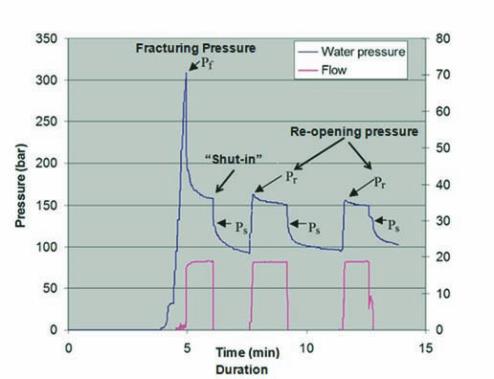
in general the same. An example on
the typical execution of stress mea-
surement with hydraulic splitting is
shown in (Figure 1), where the closing
pressure (P
S
)represents the minimum
stress component
In Norway, typical grout principles
are presented in drawings attached
to the tender and contract documents
including trigger values for grout on
demand. Further such drawings or
specifications will include maximum
inflow rates and the clients/contractor
would agree on how to perform the
works when it comes to execution.
The contract provides specification
to material as this is a remeasur-
ment item. A typical trend in Norway
over the last decades is an increased
number of grout holes being employed
for road and rail way tunnels in
urban areas, or sections with strict
requirements. In some cases as many
as between 60 and 70 holes have
been applied for such cross sections.
Another trend that has been observed
in Norwegian tunnelling over the last
5-10 years is that the introduction of
micro-cement has not reached the pop-
ularity as would have been expected,
rather it seems as the application of
ordinary portland cement maintains to
be the dominating
cement type to be
used. This might
be attributed to
the additional
material cost
of micro fine
cement which
is probably 3-5
times higher than
OPC and the fact
that owners do
not materialise
the savings in
reduced time
and quantities,
improved setting
control and grout
stability being associated with micro-
fine cement for grouting.
Even though the use of ordinary
portland cement as the main grout
mean implies a large quantity of
cement to be used, in many cases the
consumption of grout reaches several
tens of tons and even more, occas-
sions on above 100 tons have been
experienced in single grout rounds
before the planned sealing criteria is
achieved. This is far more than would
be required to establish a impermeable
zone of rock surrouding the tunnel.
And the time of performing such
grouting is becoming extremly long
when such high quantitites of cement
is applied, this again leads in fact to an
increased cost for the grouting works.
Norwegian grouting strategies
compared to that applied in
Sweden
Both (Garshol, 2002 & 2003) and
(Grøv, 2008a) provide a description
of Norwegian grouting practice, fol-
lowing the arrow. To the list below a
second numbering is complemented
to address the concept of the Swedish
way, following the circle and italic
fonts. The most important elements
are shown in the table on pages 44 &
45.
The grouting procedure of two Scan-
dinavian tunnels; the Bærum tunnel
and Nygård tunnel, two forest tun-
nels, are compared in Table 3 (page
45). The Bærum tunnel consisted of
cambrosilurian sedimentary slate, lime
and sandstone with intrusive dikes.
The Nygård tunnel mainly consists
of gneiss, granitic gneiss with some
amphibolite dykes. Further details on
fracture degree and characteristic are
not available on an overall perspective.
Methodology
To be able to compare different tun-
nels and applied grouting pressures
distinctions must be made on charac-
teristics of tunnels, grouting technique,
equipment and somewhat the grouting
materials used. If the main purpose
is in all cases to have control of the
Figure 1. The principles of hydraulic splitting tests.