Basic HTML Version


www.geotechnicalnews.com
Geotechnical News • September 2014
23
GEOTECHNICAL INSTRUMENTATION NEWS
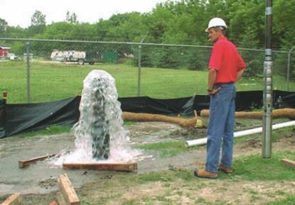
Figure 1. Big Rock Mesa Landslide – Malibu, California.
the type of monitoring that was
performed, how the data that were
collected differed from the expected
results, and how those discrepancies
were ultimately resolved. The type of
instrumentation associated with these
case histories includes inclinometers
and piezometers.
Upslope inclinometer offsets at
Big Rock Mesa Landslide
The first case history involves a large
(200+ acre) landslide in Malibu,
California referred to as the Big Rock
Mesa Landslide (see Figure 1). The
landslide activated in 1983 after an
extended period of heavy rainfall. The
basal rupture surface of the landslide
was up to approximately 250 feet deep
with a series of apparent secondary
failures along the steep coastal bluff.
The general orientation of the basal
rupture surface was defined using a
series of inclinometers. A simplified
cross section through the landslide is
provided as Figure 2. One of the incli-
nometers was installed along the top
of the coastal bluff. That inclinometer
indicated progressive shearing in an
upslope direction with no offsets in the
apparent direction of landslide move-
ment. This data initially confounded
a number of investigators and it was
speculated that either the orientation
of the inclinometer axes had been
recorded incorrectly or the inclinome-
ter casing was twisted or rotated above
the depth at which the movement
was occurring. Both of these poten-
tial explanations were evaluated and
disproved. A finite element model of
the landslide was developed to evalu-
ate stresses and deformation patterns
within the mass (see Figure 3). This
model indicated the abrupt upward
curvature of the basal rupture surface
which occurred along a fault that
extended along the shoreline would
indeed induce a stress pattern consis-
tent with the reverse shearing observed
in the inclinometer. To further evaluate
the results predicted by the computer
model, a 1:50 scale physical model of
the landslide was created (Figure 4).
The physical model consisted of a ¼“
thick piece of aluminum plate that was
bent to match the shape of the basal
rupture surface. The upper surface of
the aluminum plate was then covered
with a thin layer of wax. Fine, moist
sand was then placed on the alumi-
num plate and molded to conform
to the topography of the landslide. A
small amount of powdered bentonite
was mixed with the sand to provide
a scaled level of apparent cohesion
consistent with the formational materi-
als that comprised the landslide. The
simulated landslide failure surface was
then slowly heated using a series of
thermal strips attached to the bottom