56
Geotechnical News March 2011
WASTE GEOTECHNICS
sand (STP-07-159-SS). This zonation,
which may reflect differences in
redox conditions, provides a means
of monitoring the interaction of PA-
injectate within two chemically distinct
layers of the aquifer. Slug testing found
the hydraulic conductivity to be 6.4 x
10-3 m s-1 in the shallow zone and 2.4
x 10-3 m s-1 in the deeper region, while
groundwater chemistry suggests the
entire aquifer may be mildly anaerobic.
A nest of multilevel monitoring
points was constructed in June 2008, in
the estimated down-gradient direction
from each injection well (Figure 4).
These wells improve the researchers’
ability to identify local groundwater
flow direction and velocity and per-
mit study of injectate-aquifer interac-
tions over greater residence times. Nest
STP-08-158A was installed 3.7m from
STP-07-158-SS and STP-08-159A was
positioned 8.6m from STP-07-159-SS,
at an approximate bearing of 200 de-
grees S/SW from the injection wells.
Difficulty in precisely characterizing
local groundwater flow patterns pre-
cluded more distal placement of these
nests.
Injection and Sampling Well
Assembly
Each injection well is instrumented
with an inflatable packer, pump
and data logger to aid in the aquifer
injection experiments. A Schlumberger
CTD-Diver data logger continuously
records pre- and post-injectate
groundwater temperature, pH and
electrical conductivity. During injection
experiments, the Hoskin Scientific Ltd.
RST Instruments N-Packer is used to
seal the well screen from the overlying
stagnant water in the well and a
Grundfos Redi-flo2 submersible pump
is used to sample the groundwater.
Injections themselves are driven by
the ~15m difference in hydraulic head
between the discharging tank and the
water table. The components were
assembled in-house such that tubing
and wiring pass through the packer
(positioned just above the well screen)
to the probe and pump (aligned within
the well screen), thereby allowing
for samples and measurements to be
taken with the packer inflated and
in place. Lastly, each down-gradient
multilevel well is also equipped with a
Schlumberger CTD-Diver.
Continuous core samples were col-
lected within the Wood Creek Sand
Channel for grain size, falling head
permeameter, fraction of organic con-
tent, calcite and dolomite content, an-
aerobic microcosms, and sequential
extraction procedures (to assess the
partitioning of trace elements within
the solid phase).
Other Available Suncor
Facilities
Additionally, Suncor hasmadeavailable
to this project the use of pressure relief
wells at the toe of the dyke, internal
dyke drains and its own extensive
network of monitoring wells as well as
their historical sampling records. This
offers the project a means to further
corroborate and extrapolate findings
beyond the localized boundaries of the
three research facilities.
Conclusions and Outlook
In Northern Alberta, it is expected that
the placement of out-of-pit tailings
ponds atop permeable, glaciofluvial
sand channels will become increasingly
prevalent. This project is the first of
its kind to investigate the lifecycle
of process-affected water seepage
from an oil sands tailings pond in
this setting – beginning with in situ
background conditions, through to
seepage migration and evolution,
and culminating with preliminary
investigation into potential mitigation
strategies. This research is expected
to benefit the entire oil sands industry,
with ramifications extending to the
future placement of tailings ponds,
remediation and mine closure strategies
and legislation for environmental
compliance.
Acknowledgements
The authors wish to acknowledge
Suncor Energy Inc., NSERC, the
Alberta Innovates Technology Futures
and Klohn Crippen Berger Ltd. for
supporting this project.
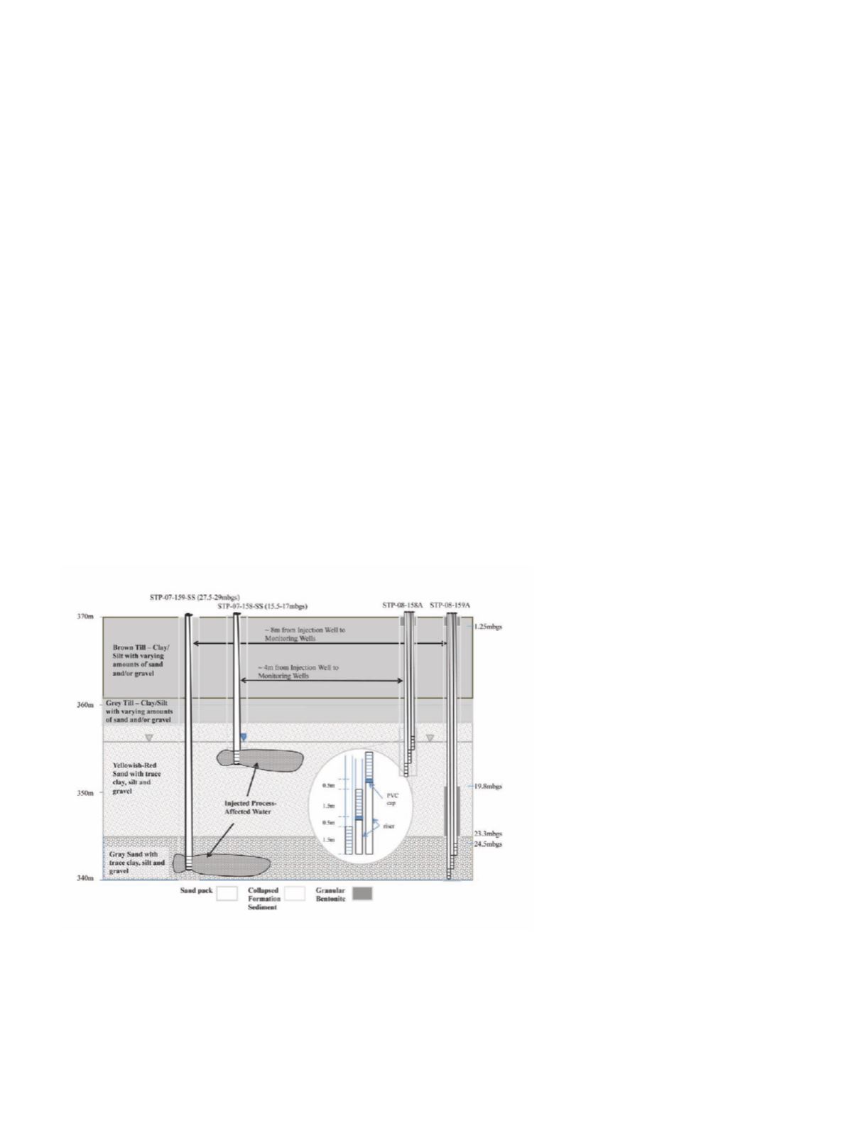
Figure 4. Cross-section schematic of wells at the In Situ Aquifer Test Facility.
Each multilevel nest was instrumented with three, 2.5cm diameter, Schedule 40
PVC wells. Well screens were hand-slotted using a hacksaw and wrapped with fil-
ter fabric to prevent ingress of sand. To facilitate installation of each screen at the
target depth, a section of 2.5cm Schedule 40 PVC riser was subtended to the well
screen. A PVC cap was mounted between the base of the well screen and the riser
top, to prevent the accumulation of water in this section beneath the screen. (mbgs
= metres below ground surface, elevation (m) in metres above sea level)


