Basic HTML Version


www.geotechnicalnews.com
Geotechnical News • March 2014
33
GEOTECHNICAL INSTRUMENTATION NEWS
active construction for the following
reasons:
• During measurements the link
between eye-bolts creates a physi-
cal barrier. This can cause costly
delays, as equipment that can pass
by is restricted.
• Measurements are often rushed
because of pressure from sur-
rounding workers delayed by the
physical barrier.
• A second person is sometimes re-
quired, often assisting on a ladder,
to hook the second end of the tape
to the eye-bolt, which increases
monitoring costs.
• Eye-bolts protrude from the
monitored surface, and are easily
damaged or bent by construction
activity.
• The tape extensometer can be cum-
bersome to transport.
• Ambitious construction schedules
and time constraints on workers
means that an often time consum-
ing and disruptive measurement
process is easily overlooked.
Introduction of the laser-
distometer alternative
These difficulties inherent in monitor-
ing with a tape extensometer mean
that readings may be skipped or
rushed just when data collection is
most needed. An alternative method
of measuring deformation is to use
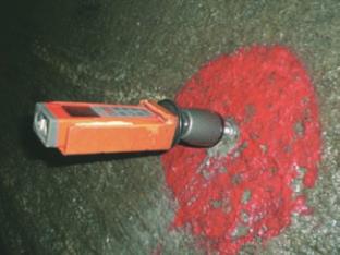
a laser-distometer and targets. The
laser-distometer is placed into a cradle
at one point (Figure 2), the laser beam
is reflected from a target at the second
point, and captured again by the
laser-distometer. The distance is then
calculated within the instrument by
recording the interval of time between
sending and receiving the laser pulse.
The authors have not found hard
evidence of laser-distometers being
specified or permitted for tunnel
deformation monitoring before late
2006. At that time instrumentation
specifications for New York City Tran-
sit’s 7 Line Subway Extension were
modified by the designer, the Parsons
Brinckerhoff Team, to include the fol-
lowing statement, “In tunnels driven
by TBM, Contractor may consider
the use of laser measuring devices in
lieu of tape extensometer convergence
bolts in order to begin measurements
as close as possible to the back of
the tunneling machine. Such devices
shall be able to achieve an accuracy
of 1/16-inch or better across a space
of 20-feet. Spot markers and reflec-
tive targets shall be provided to ensure
that readings can be repeated at the
same monitoring points as the tunnel
progresses.” This specification was
published in January 2007 in time for
the bidding of tunnel construction,
but the construction contractor who
won the job did not choose the laser-
distometer option.
The laser-distometer measurement
alternative had not been offered in the
specifications for the Metropolitan
Transportation Authority’s East Side
Access Project, for which the start
of design had preceded the 7 Line
Subway Extension’s design by several
years. However, when the time came
to excavate the project’s connecting
tunnels and enlarge the cavern beneath
Grand Central Terminal in 2007, it
was obvious that up-to-then standard
methods of deformation monitoring
faced some great hurdles. Discussions
were begun with the construction con-
tractor and an agreement reached that
led to a contract modification calling
for any tape extensometer measure-
ments of tunnel and cavern deforma-
tion to be replaced by laser-distometer
measurements.
The laser-distometer in practice
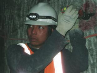
A portable cradle for the distometer
should be fabricated, and attached to
an anchor bolt at the first point with a
swiveling head (Figure 3). The reflec-
tive target at the second point should
be small (approx. 2-inch diameter) and
mounted with its face perpendicular
to the direction of the laser beam from
the first point. The laser-distometer
uses electronic distance measurement
technology, which is commonly used
in the surveying industry, however
it had not necessarily been tried and
tested in this application.
Project specifications will generally
specify use of the tape extensometer,
yet the laser-distometer offers many
advantages over the former method.
Some of these are:
• No physical barrier is created when
taking readings.
• Reduced setup and reading time.
• Only one person is required and no
direct access to the second target is
necessary.
• The laser-distometer is small, light-
weight and can be easily trans-
ported in a pocket.
• The likelihood of a greater number
of measurements being recorded is
higher, due to a simpler data col-
lection process.
• A lesser “nuisance” factor while
taking readings may result in the
collection of better quality data.
Laser-distometers with millime-
ter accuracy are widely available,
and in most cases are considerably
less expensive than tape extensom-
eters. The advantages of the laser-
distometer over the tape extensometer
are obvious to these authors and to
Figure 2. Laser-distometer in cradle.
Figure 3. Laser-distometer reading.