Basic HTML Version


www.geotechnicalnews.com
Geotechnical News • September 2014
33
THE GROUT LINE
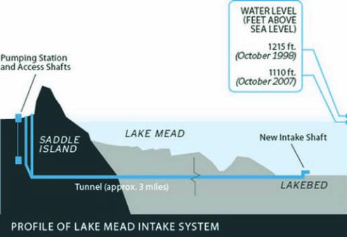
located in the largest reservoir of the
United States, that was formed by
the Hoover Dam and which extends
across the Colorado River between
Nevada and Arizona. Due to the
constant drawdown of the lake level
in the last 15 years, the new intake
will lay at a depth greater than the two
intakes that are in operation. The water
autority forecasted that there is a high
risk that Intake No. 1 could be dry
by 2020, resulting in the impossibility
of the water supply infrastructure to
satisfy the overall demand from the
Southern Nevada region. This risk can
be overcome by the construction and
operation of Intake No. 3.
In March of 2008, the Vegas Tunnel
Constructors (VTC) joint venture,
formed by the Italian company Salini-
Impregilo SpA and the American
company SA Healy, was awarded by
the Owner (Southern Nevada Water
Authority - SNWA) the contract for
the construction of the Lake Mead
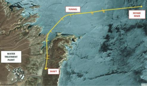
Intake No. 3 project. The project
includes fabrication and positioning an
intake riser, excavation and lining of a
185 m deep shaft and construction of a
4.6 km (Figure 1) tunnel by means of
a tunnel boring machine (TBM).
TBM description
The tunnel boring machine designed
to excavate the 4.6 km intake tunnel
is a Herrenknecht shielded machine. It
is a hybrid prototype with the capabil-
ity of excavating the ground either in
open or closed mode, depending on
the hydro-geological conditions of the
encountered rock masses (Figure 2a
and 2b).
The open mode operation consists
of excavating the ground without
any face support and discharging the
excavated material through an 18 m
horizontal screw conveyor. This feeds
a system of belts which runs along the
TBM trailing gear, along the lined tun-
nel and terminates at the bottom of the
shaft, where the muck is discharged
into two buckets. Each bucket has a 15
m3 capacity and runs vertically up the
180 m deep shaft, bringing the mate-
rial to surface. Once at the surface, a
550 m long belt conveyor system is
loaded to take the muck to the desig-
nated disposal area on site.
In closed mode, the TBM operates like
a slurry machine. Mining occurs by
applying a support pressure at the face.
This mode is used in order to guaran-
tee stability of the ground avoiding
any uncontrolled muck handling and
to reduce the risk of tunnel flooding in
case highly permeable rock masses are
encountered or direct connection with
Lake Mead is made. The supporting
pressure is applied by injecting ben-
tonite drilling mud in the excavation
chamber. This is also used as a means
to remove the excavated material from
the heading. A mix of bentonite and
muck, called slurry, is transferred to
the surface through a system of pipes
and pumps running along the TBM
then down the lined tunnel and finally
the shaft. On the surface, the slurry is
pumped to a separation plant where
the excavated solids are removed and
the drilling mud is recycled through
the slurry circuit.
The machine is designed to withstand
a maximum hydraulic head pressure
of 17 bar and operate at 15 bar. The
cutterhead is equipped with no. 48
cutters, 17” diameter resulting in an
excavation tunnel diameter of 7.22 m.
The cutterhead and the total installed
power required are 2,800 kW and
5,750 kW respectively. The breakout
torque is 10 MNm. The nominal and
the maximum thrust are 70,000 kN
and 100,000 kN respectively.
The shield is composed of 3 main
parts characterized by different diame-
ters in order to obtain a conical shape:
Front shield (7.18 m), Middle shield
(7.16 m) and Tail shield (7.15 m). An
articulation joint is located between
front and middle shield. The machine
including the cutterhead and shields
is 15 m long and weighs 900 tons. All
the equipment necessary to operate the
TBM is installed on 15 gantries, a total
length of 175 m and a total weight of
600 tons.
Among many special features, the
TBM is equipped to handle high water
pressure and inflows. The machine is
equipped with no. 3 drill rigs in order
to perform either geological investiga-
tion (probing and coring) or pre-
excavation ground treatment to reduce
the permeability and/or increased
Figure 1. Project plan and profile.