Basic HTML Version


30
Geotechnical News • December 2014
www.geotechnicalnews.com
THE GROUT LINE
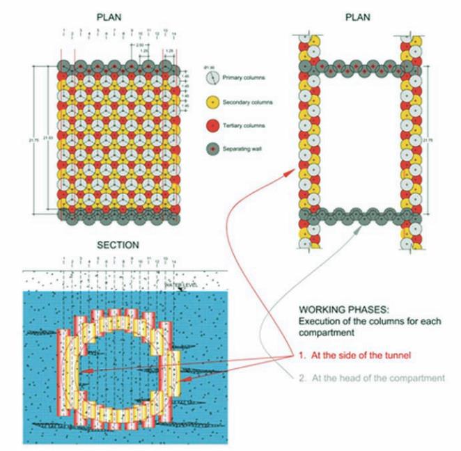
tertiary columns were lengthened
so as to create plugs that sealed any
residual imperfections between the
primary and secondary columns. Each
compartment was separated from the
successive one by buffer columns.
Each of the 38 compartments con-
sisted of approximately 400 verti-
cal columns (see Figure 4). Where
constraints at the surface exist, i.e.
next to the motorway junction, the col-
umns were inclined. For this reason, a
special QA/QC program was imple-
mented to assure that each single col-
umn was drilled at the correct angle,
in the correct position, and using the
correct parameters.
In total 9,000 boreholes were drilled,
for the construction of 15,300 jet
grouted columns positioned in the
upper part of the tunnel, in the lower
part and at the sides. In total, 210,000
linear meters of holes were drilled,
with a maximum length of 35 m. The
total consumption of dry binder was
160,000 tonnes, i.e. up to 800 tons of
binder per day.
Quality control
Quality control was particularly strict
to comply with the rigid tolerances
allowed by the project, both during
the project phase and the execution of
the jet grouting. Before work began,
TREVI developed a 3D-modelling
system (see Figure 5), to assess the
overlap of each column with the adja-
cent one. During the execution phase,
the axis of the columns was deter-
mined with a topographical device,
and its positioning was monitored by
the a down-the-hole probe. All data
were subsequently conveyed to the
technical office and to quality control.
To this end, a series of devices were
used:
1. Topographical instrumentation for
the accurate installation of the
equipment;
2. Automatic recording device to
record the data of drilling and
jetting;
3. Down-the-hole survey probe to
measure the actual direction of
drilling axis.
The data collected from each device
were used for the modelling of the
geometrical data. Finally, using the
actual diameters of the columns, the
3D-model was checked to measure
the actual overlapping of the columns.
The different length of each column,
determined by its location and its
position in the sequence, just added
complication to the system.
In order to speed up the process, with-
out impairing the accuracy, a system
was created to guarantee a quick man-
agement of parameters obtained from
the devices, involving the management
of two databases. Each drilling rig was
equipped with 2 prisms located at the
mast’s top and base, so as to allow a
careful positioning by focusing them
thanks to an automatic total station.
The starting coordinates of each hole
had to be entered into the software of
the borehole survey probe.
Database 1 contained the design data,
and it was used at the planning stage
of each working day. It contained the
relevant data of each column: position-
ing coordinates according to different
local systems, the treatment’s depth
data (top and bottom depths of each
jetting interval), jetting parameters,
etc. Said data made it possible to set
up the automatic parameters recording
device. In order to supply each team
with the relevant information for the
correct execution of each column in
a timely manner, a tag was automati-
cally generated for each column by the
database 1, by selecting the column
number in the computer.
The second database contained the
as-built data of each column, collected
from the data returned by the record-
ing devices. This database, thanks to
an automatic calculation system, was
capable of checking the minimum
dimensions of the overlapping area
Figure 4. Pattern of columns for each compartment (typical).