Basic HTML Version


www.geotechnicalnews.com
Geotechnical News • December 2014
31
THE GROUT LINE
between pairs of columns. Moreover
it allowed for the calculation of the
starting coordinates of a possible addi-
tional column, in case the target was
not reached.
The data contained in the database
were used to create the 3-D model of
the installed columns. Starting from
the model, a plan view with four
transverse sections and a longitudinal
section for each section was created.
A 3-D drawing was created for each
compartment, allowing the extrapo-
lation of some sections at different
depths.
Final control and results
The final controls were focused
on assessing the strength of the jet
grouting bodies, and the final perme-
ability. To this end, corings were used
to collect samples to be tested for
crushing tests, and pumping tests were
performed to measure the resulting
quantity of water.
As said, the design was asking for
a minimum uniaxial compressive
strength of 5MPa: the tests gave a
minimum strength of 8MPa.
The compartments were all success-
fully tested using pumping tests. The
average water flow was measured in
2.5 liters per second (compared to the
5 liters per second tolerated by the
design).
Conclusions
The method proposed by Trevi
enabled the achievement of the desired
features in terms of water tightness
and strength requested by the design.
In spite of the complex geology,
where the groundwater was running
at high velocity, the excavation of the
tunnel 20 m below water table and 32
m below grade, has been performed
safely without major difficulties, in
dry conditions.
Last but not least, to be noticed that
the railroad was continuously operat-
ing 365/7/24 during the execution
of the jet grouting works with only
a slight reduction in the speed of the
trains. For safety purposes, potential
movement of the railroad tracks were
monitored in real time and no issues
were observed during the execution of
the jet grouting works.
References
Greeman, A., 2009:
Cutting through
Austria’s Inn Valley
. Tunnels &
Tunnelling International, Novem-
ber, pp.16-19.
AA.VV., 2010:
From the ground
down
. World Tunnelling, March,
pp.10-11
And, as usual, the same request,
asking you to send me your grouting
comments or grouting stories or case
histories. My coordinates are:
Paolo Gazzarrini,
,
or
Ciao! Cheers!
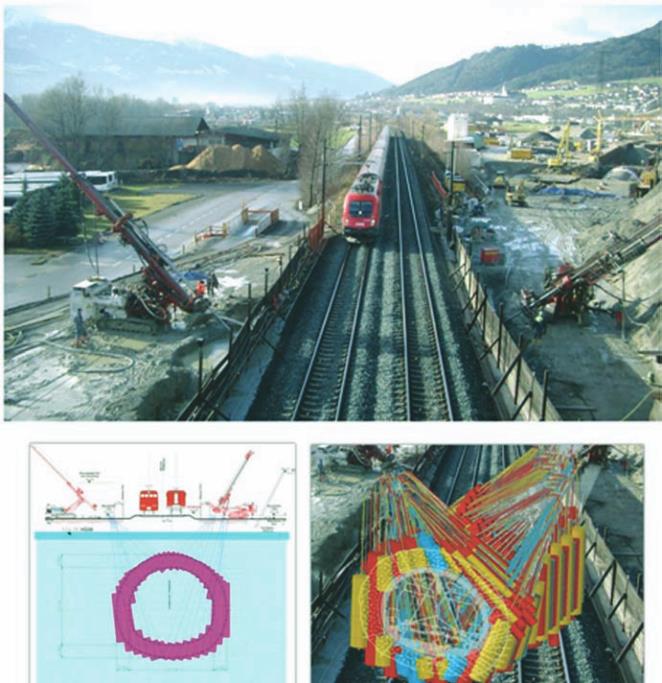
Figure 5. Panorama of two rigs working on the two sides of the existing
railway line. At the bottom, the cross section (left) and a 3D view of the final
shell created by the jet grouting (right).