Basic HTML Version


www.geotechnicalnews.com
Geotechnical News • December 2014
39
GEOTECHNICAL INSTRUMENTATION NEWS
fully-grouted installations. There was
often a strong perception that the
groundwater pressure outside of the
grout column would not be fully trans-
mitted through the grout to the embed-
ded sensors. The low permeability of
a typical grout mixture (about 1 x 10
-6
cm/sec) contributed to this perception.
Simple one-dimensional calculations
suggested that an extended period
of time (i.e. hours to days) could be
required for a transducer embedded in
low permeability grout to respond to
pressure changes outside of the grout
column. These calculations contrib-
uted to the skepticism.
In order to evaluate the transducer
response and associated time lag,
several pneumatic
and vibrating wire
transducers were cast in grout cylin-
ders ranging from 3“ to 10“ in diam-
eter. Each of the transducers was fitted
with a 0.4” diameter by 1” long porous
polypropylene filter tip. The length
of each test cylinder was twice its
diameter. After curing for at least 24
hours, the test cylinders were lowered
into a 1 foot diameter by 8 foot long
standpipe that was filled with water.
The test cylinders were typically
lowered two feet at a time and moni-
tored continuously until steady state
pressures were recorded. The results
of a typical test series with pneumatic
piezometer transducers
are shown in
Figure 1. As indicated, the transducers
were found to respond rapidly to the
pressure changes. In each case, steady
state readings were obtained within 60
seconds, or less, of moving a test cyl-
inder to a deeper or shallower depth.
The stabilization time was found to be
more or less linearly proportional to
the diameter of the test cylinder. For
all tests, the steady state readings were
found to correspond to the depth of the
tip of the sensor within the accuracy of
the measurement (±0.5“). These test-
ing results, and real time demonstra-
tions, were used to convince clients,
consultants, and regulators that the
fully-grouted installation procedure
Figure 1. Response time lag for pressure transducers cast in grout cylinders.
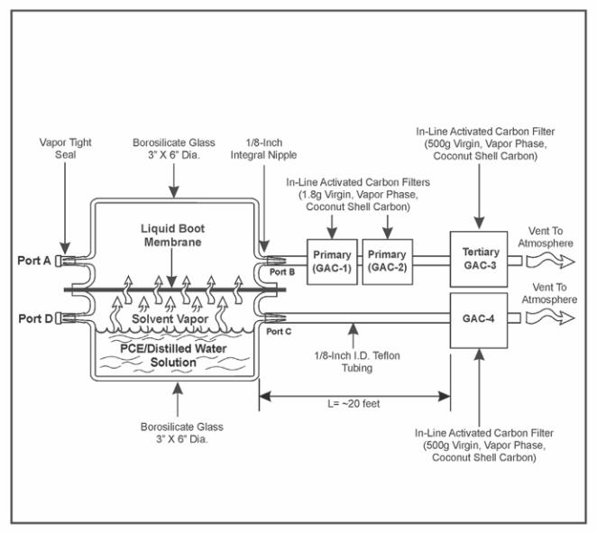
Figure 2. Vapor barrier diffusion test configuration.