Basic HTML Version


40
Geotechnical News • December 2014
www.geotechnicalnews.com
GEOTECHNICAL INSTRUMENTATION NEWS
was a viable, and typically superior,
alternative.
[I’m concerned about this apparent
green light for installation of pneu-
matic piezometers by the fully-grouted
method. There are several types of
pneumatic transduces, including those
that are read as gas is flowing past the
diaphragm and, very preferably, those
that are read under a condition of no
gas flow immediately after the flow is
stopped. In the latter case a volume
change occurs in the pore space at
the instant of reading (red book Sec-
tion 8.3). I’ve always contended that
this feature negates the use of the
fully-grouted installation method for
installation of pneumatic piezometers.
I made this point to the author of this
article, who replied: “With respect to
the diaphragm displacement issue with
the pneumatic transducers, we can
create a situation where the pressure
response oscillates as the diaphragm
opens and closes (but gradually con-
verges on a stable reading) if we cast
the transducer without a filter tip. With
a filter tip, we have never experi-
enced that type of oscillation – out of
several hundred installations. We have
read the grouted-in-place pneumatic
transducers both ways – with a slow
constant air flow through a needle
valve and by over-pressurizing the tip
and allowing the pressure to drop and
stabilize – both yield the same results
within about an inch of water col-
umn”. Despite this reply, I’m reluctant
to change my contention and support
the green light.
Does anybody have
anything to contribute to this?
J.D.]
Sub-slab vapor barriers
The second case involves the moni-
toring of soil gas sampling probes
installed above a sub-slab vapor
barrier. Engineered vapor barri-
ers are frequently installed beneath
buildings that are constructed at sites
where Volatile Organic Compounds
(VOCs) such as solvents, gasoline,
or other hydrocarbons are present
in the subsurface. The barriers are
intended to reduce the rate at which
VOCs would otherwise migrate to the
interior air spaces of buildings. Post-
installation monitoring and evaluation
of the performance of sub-slab vapor
barriers is becoming an increasingly
common requirement at contami-
nated properties. Soil gas sampling
probes are often installed above and
below a vapor barrier to confirm that
it is functioning as expected. There
is a common perception that vapor
concentrations above a barrier should
be very low - if not below detectible
levels. The presence of elevated
vapor levels in the space above a
vapor barrier and below a floor slab
is frequently taken as an indication
that the barrier is not functioning
properly. This interpretation is not
necessarily correct. All vapor barriers
will transmit VOCs to some extent.
The purpose of the barrier is to limit
the rate of VOC transmission to the
interior of a building such that accept-
able risk thresholds are not exceeded.
High quality, intact concrete also
provides considerable resistance to the
transmission of many organic vapors.
Although a concrete floor slab can
typically not be relied upon to func-
tion as a vapor barrier for a number of
reasons, the characteristics of the floor
slab need to be considered when data
from sub-slab vapor probes is to be
used to evaluate the performance of an
underlying barrier.
The diffusion coefficients for a num-
ber of vapor barrier materials have
been measured for various VOCs
using the test configuration illustrated
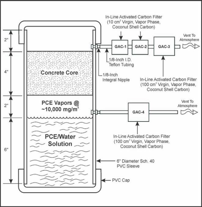
in Figure 2. Similar tests have been
performed to measure the vapor diffu-
sion coefficients for concrete (Figure
3). As shown, for both the membrane
and concrete tests, a water reservoir is
maintained in the lower test chamber.
VOCs are dissolved in the water to
Figure 3. Concrete slab diffusion test configuration.