18
Geotechnical News •June 2015
GEOTECHNICAL INSTRUMENTATION NEWS
80 mm to 200 mm. The rockfill shell is
comprised of two zones: the 3O inter-
nal shell has a maximum allowable
size of rock particles of 0.6 m com-
pared to 1.2 m for the 3P outer shell.
Figure 1 shows a schematic cross sec-
tion of the dam at valley center.
Material placement procedures were
of utmost importance to prevent
excessive fill movements during dam
construction and operation which
could have detrimental effects on the
thin asphalt core. The placement of
support/transition as well as rockfill
zones required optimized material
characteristics and increased com-
paction energy to achieve maximum
density and thus minimize settlements
during construction, impoundment
and operation. Therefore, internal
deformations of the dam needed to be
closely monitored to assess its behav-
iour as well as in situ materials rigidity
parameters to be used for stress/defor-
mation modelling and also to quantify
the effects of the increased compac-
tion energy used for the Romaine-2
dam compared to other Hydro Québec
projects.
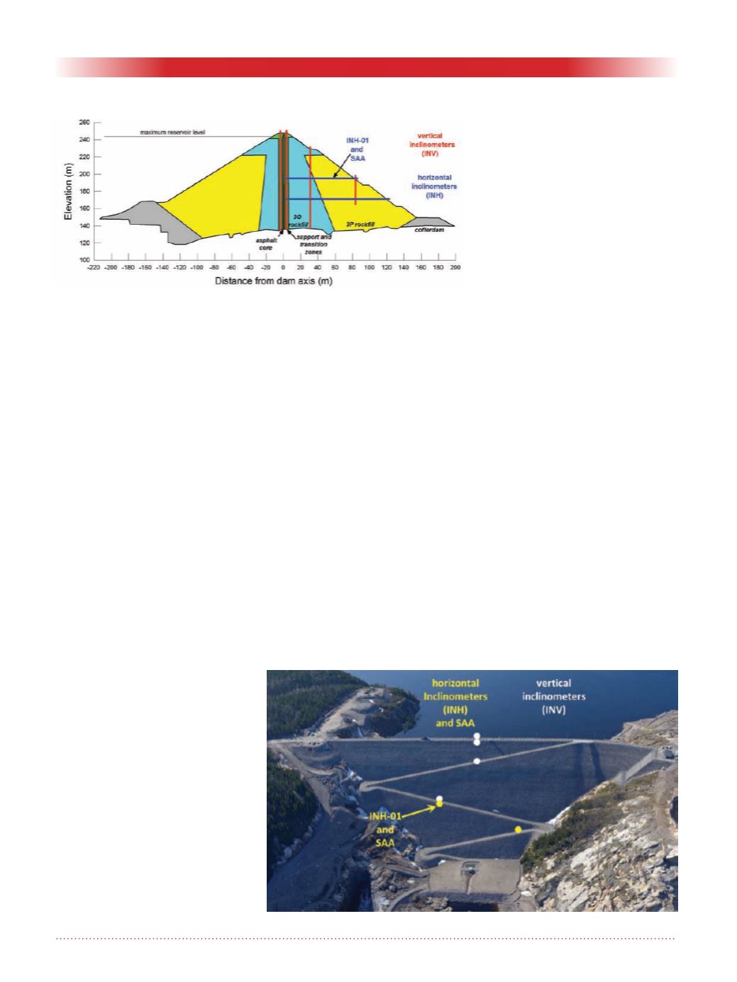
A series of inclinometers is installed
in the dam body to measure deforma-
tions (see Figure 1). A total of four
vertical inclinometers (INV) anchored
in bedrock (far end considered fixed)
are used to monitor movements closer
to the core as well as in the 3O and
3P rockfills. The INV in the 3P zone
represented on Figure 1 is located at
a section where bedrock elevation is
higher. Two horizontal inclinometers
(INH) and one ShapeAccelArray
(SAA) are also installed to monitor
settlements. The far and near ends of
these three instruments are not consid-
ered fixed. Figure 2 shows the location
of the INV, INH and SAA.
The SAA is installed along INH-01
(see also Figure 1). An access road on
the dam crest and downstream face
allows instrumentation readings.
INH characteristics
The two INH are composed of 1.5
m-long grooved ABS casings installed
horizontally in a trench excavated in
the placed rockfill. Settlement read-
ings are made using an accelerometer
probe which measures tilt at every 0.5
m in the plane of the probe wheels
travelling in the top and bottom
grooves of the casings. The probe is
inserted in the horizontal inclinometer
using a system of return cable and pul-
ley. The return cable is installed within
a separate pipe alongside the incli-
nometer casing. The tilt measurements
from two sets of readings (probe
reversed end-for-end) are converted to
settlements at the office.
INH were installed in other Hydro
Québec projects but have been subject
to operation problems after two to
three years due to ice build-ups inside
the casings as well as pulley and return
cable malfunctions. These problems
had a significant effect on the avail-
ability and the reliability of results.
Long-term settlement monitoring
along a horizontal plane gives valuable
information related to the deformation
of the various types of materials con-
stituting an embankment dam. Defor-
mations need to be measured during
the construction (load increase due to
fill placement), impoundment (load
due to reservoir) and operation (creep)
phases of the dam life cycle. Another
option was thus needed to obtain
reliable settlement measurements. A
SAA was therefore installed in the
Romaine-2 dam to gain confidence in
this relatively new technology.
SAA characteristics
A SAA consists in a series of rigid
segments separated by special joints
which can tolerate the range of settle-
Figure 2. Location of inclinometers and SAA.
Figure 1. Schematic cross section of the Romaine-2 dam and location of
inclinometers and SAA.


