Geotechnical News December 2011
53
GEO-INTEREST
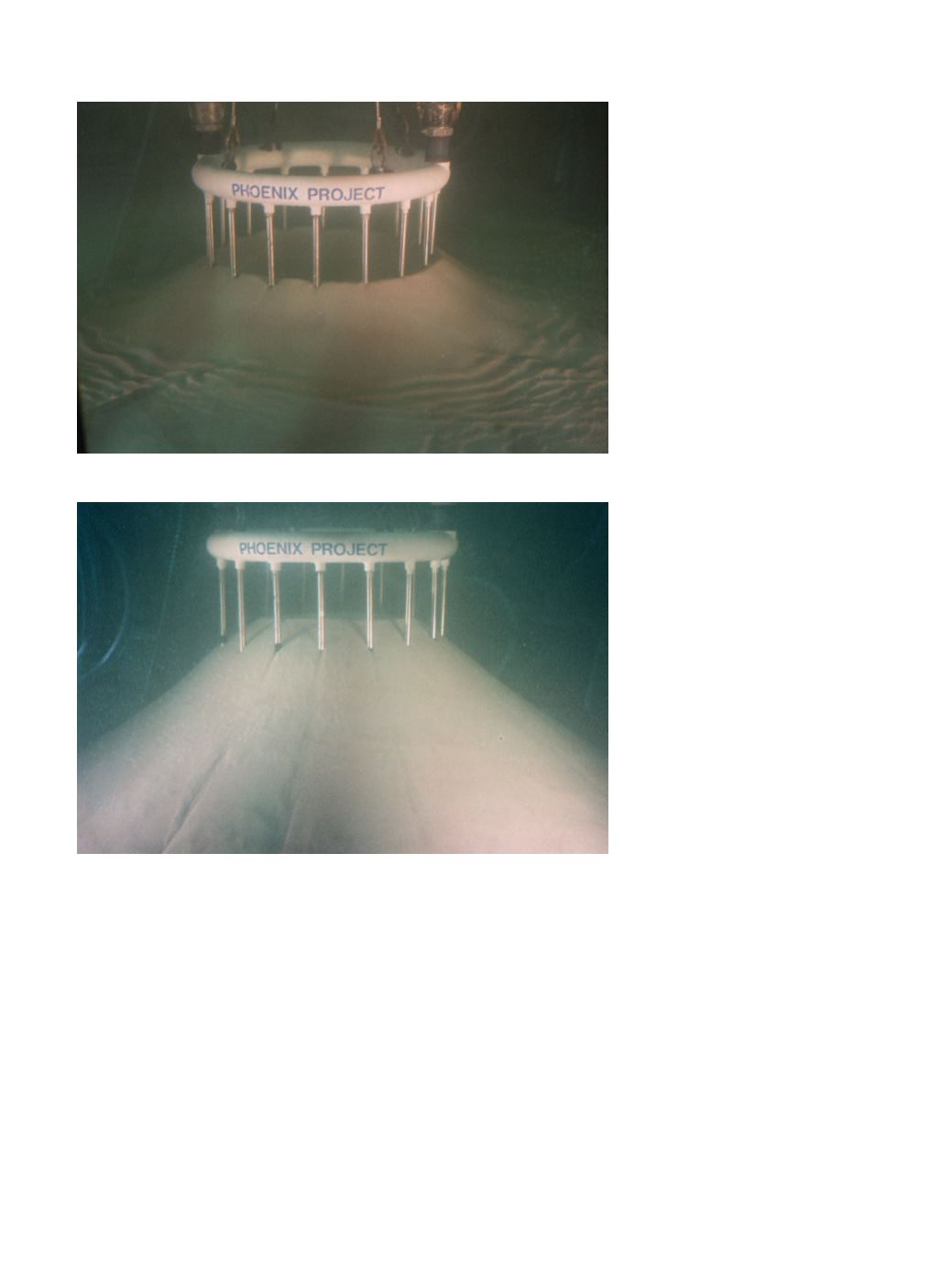
Figure 14b was taken during an in-
terruption in sand placement. It can be
seen that, at this stage, the sand is accu-
mulating in a ring around the alignment
of the well screens. This establishes
that where the S
f
is intense/concentrat-
ed enough to be potent, sand particles
can be captured from the jet.
The Seepage Force is now acting in
reverse (to its natural tendency). It is
working to our advantage.
Figure 14c shows the sand pile
which resulted after the wells had been
progressively elevated (by gradually
hoisting the circular header) as the slur-
ry jetting continued. Average slopes of
up to 38° were achieved, with slopes
locally as steep as 45° nearer the well
screens. These slopes, built dynami-
cally in the abrasive environment of
the impinging jet, significantly exceed
the 29° submerged angle of repose
achieved by placid means, but without
the aid of an inward S
F
.
Two important geotechnical forces
are to be seen at work in these photo-
graphs and model results: the forces of
Drag and Seepage.
1. Discrete sand particles jetting down
the slope of the model are literally
dragged into the face of the slope,
and then secured in place, by the
water velocity created across them
by inwardly flowing water.
2. Otherwise overly-steep side slopes,
of non-cohesive material, are made
stable in a severe hydrodynamic
context by the potency of the S
F
as
it pushes discrete particles into the
face, thereby greatly increasing the
effective normal stresses on them.
At a fundamental physical level
these forces are closely coupled in
their origin and influence, and perhaps
should not be spoken of as separate be-
haviours. They are both a result of rela-
tive movement between the phases, in
this case with the water doing the most
of the moving.
Now that we have recruited the con-
cept of the Seepage Force we can move
on to building a bridge between the
Drag Forces that can be calculated for
a single particle, and those forces act-
ing on the same particle size when it is
just one among a multitude of particles
of various sizes within a cramped and
crowded soil-structure.
Defining the Crowding Factor K
The approach to both defining, and
calculating, the Crowding Factor is as
follows:
It is taken that the Seepage
Force exerted on a given volume
of saturated soil due to water
flowing through it is a direct
consequence and result of the
summation of the Drag Forces
exerted on its individual grains.
Furthermore, the individual
particle Drag Forces are taken
as being equal to those proposed
by Fluid Mechanics for spherical
particles of equivalent size when
exposed to the flow velocity
existing within the voids of the
soil-structure.
The value of the ratio between
the water velocity in the void
space [v
V
], as compared to that
of the approach flow [v
A
], is K.
The definition of the Crowding Fac-
tor may therefore by stated as follows:
K = v
V
÷ v
A
such that if v
V
is applied to the cal-
culation of F
D
, then the Drag Force per
particle will be numerically equal to
the S
f
when v
A
is used in the calcula-
Figure 14b. Jetted sand accumulating around well screens.
Figure 14c. Steep underwater side slopes made by Seepage Force.


