Basic HTML Version


www.geotechnicalnews.com
Geotechnical News • September 2014
35
THE GROUT LINE
advance the quantity of water inflow.
For this purpose the TBM can be
used as a large-scale constant-head
permeameter according to the fol-
lowing procedure. Starting from its
initial value, the face support pressure
is lowered in steps of 0.5 bar. After
each step the increase of water inflow
is measured observing the change of
water outflow in the slurry line while
keeping the slurry level in the bubble
chamber constant. The final value of
water inflow is recorded after reaching
stationary seepage flow conditions. In
the present case, this normally took
less than 15-20 minutes. After several
steps (generally more than 10), the
relationship between the quantity of
water inflow and face support pressure
can be established and subsequently,
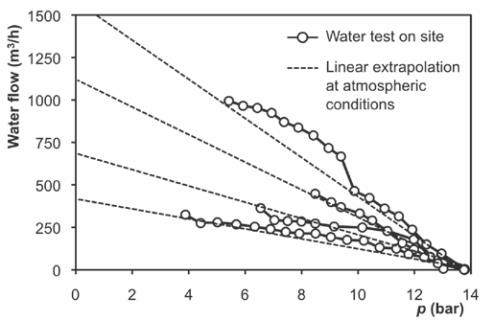
linearly extrapolated to 0 bar (Fig. 5
shows an example). This approach
allows estimating the quantity of water
inflow under atmospheric conditions
safely, i.e. without the risk of a face
instability associated with lowering
the support pressure to 0 bar.
During the water tests the force act-
ing on the cutter head, the torque (by
rotating the cutter head without TBM
advance) and the colour of the drained
water are observed in order to timely
identify the possible onset of local
instabilities and thus interrupt the test
by increasing the support pressure
immediately to its initial value. By
using the TBM as a large constant-
head permeameter, the overall perme-
ability of the rock mass (and therefore
also the effectiveness of pre-grouting)
can be estimated by numerical back-
analysis of the measured relationship
between face support pressure and
water inflow (Figure 5). It should be
noted that for high quantities of water
inflow, the relationship between face
support pressure and quantity of water
inflow was not always linear (Figure
6, upper curve). Possible reasons for
this non-linearity are turbulent flow
or closing of joints due to increasing
effective stresses around the tunnel
face.
Three large-scale permeability tests
were performed but all were aborted
at 10 bar with over 200 m3/h water
inflow.
At this point the JV opted to drill and
grout the ground ahead of the TBM
in order to reduce the permeability,
increase the overall stability and allow
men to enter the cutter head.
On a TBM machine drill and grout
operations at such high pressure had
never been done before. The ground,
mainly composed of sandy, silty and
clayey material, made it very difficult
to grout.
At this point, an inspection of the
cutter head was possible by using a
camera installed on a steel pipe and
pushing it into the excavation chamber
through a drill port equipped with a
blow-out preventer. The inspection
revealed that the cutter conditions
were not that worn, and on August
1, 2012, a further attempt to free
the machine was completed. The
face pressure was raised to 14 bar,
the penetration showed values just
above zero, however the machine
was advancing. After 12 pushes, a bit
over the length of the shield, the TBM
parameters were back to regular opera-
tion, though showing inconsistencies
on penetration and advance speed.
A plan of permeameter tests was
discussed as cutterhead inspection and
maintenance at atmospheric conditions
was a priority. Since restarting the
mining activities, during the next 77
pushes, 10 tests were performed and
the resulting water inflows reached
a maximum of 1,100 m3/h at 8 bar.
Accordingly, it was impossible to
access the excavation chamber for
maintenance. There was one excep-
tion where the face pressure was
lowered to 0 bar and the excavation
chamber was accessed. Unfortunately
the geological conditions were not
favourable to perform the cutterhead
maintenance.
On September 29, 2012, at push 235,
the TBM penetration reduced. The
camera inspections detected wear on
the cutters. The possible scenarios
were two: perform a series of pre-
excavation grouting campaigns to
allow for maintenance or prepare
all necessary equipment for hyper-
baric intervention in saturation. Both
options had never been done before
at 14 bar pressure and the hyperbaric
work had more inherent risk and cost,
so the decision was to start grout-
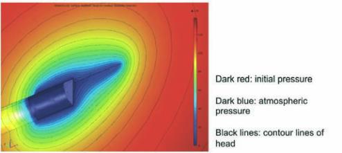
Figure 5: Interpretation of water inflow by means of
numerical seepage flow analysis.
Figure 6: Relationship between face support pressure and
quantity of water inflow.