Basic HTML Version


36
Geotechnical News • September 2014
www.geotechnicalnews.com
THE GROUT LINE
ing the ground ahead and around the
TBM.
However, the hyperbaric intervention
was still an option and the procure-
ment of the gas and equipment and
planning of the logistics was being
done concurrently with the grouting
program.
Pre-excavation grouting
campaigns: means & methods
The ground treatment ahead of the
machine was planned and based on the
GIN-method [5]. Maximum injection
pressure and maximum injection vol-
ume were defined in accordance with
the fractured ground conditions. A
significant difficulty was caused by the
fixed pattern of available drilling holes
(see green and blue dots on Figure
3). For different stages a methodical
injection sequence was followed for
the primary and secondary holes.
This was the first intensive grout
intervention at 13 bar of face pres-
sure. Normal drilling and grouting
procedures were not applicable in our
case. It was very difficult managing
the water inflow (with pressure) and
placing the packer once the hole was
drilled. In order to keep up with the
challenging geological conditions
some modifications and innovations
of the equipment were introduced. In
particular our focus was on:
• Designing an additional backflow
preventer to be installed in front of
the original one in order to prevent
water and materials coming into
the tunnel.
• Changing geometry of the drill
steels, from a T38 with round
shoulder to a T38 with a square
shoulder, in order to reduce the
friction point between the steel and
the inner rubber of the backflow
preventer.
• A packer and the casing had to be
designed in-house, to be able to in-
stall the packer in highly fractured
material. The casing allowed us
to install the packer at the correct
location and inflate it without dam-
aging the backflow packer.
• Different size and configuration of
drilling bits.
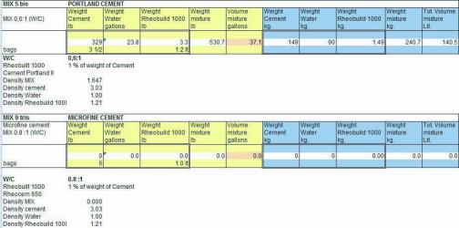
• Different mix designs were used
depending on the fractured rock
mass. Portland and Microfine
cement were both used as per the
mixes shown in the table below:
A total of three pre-excavation grout-
ing campaigns were performed (Figure
7 and Figure 8).
The first grouting campaign was car-
ried out at ring #235, STA 18+65. The
area grouted was planned to extend
11 m, which covered the upper part
of the layout shown in Figure 3. The
campaign was completed in 1 month
then the TBM was advanced 4 m. 1st
Campaign - Technical data:
• Number of holes drilled: 22 holes
• Total length drilled: 278 m
• Total quantity injected: 43 m3
• Volume injected: 155 l/m
The second campaign was performed
at ring #237, STA 18+79. The grouting
was increased to 15 m with an overlap
of 4 m of the first campaign. Grout
injection was done through the entire
pattern of available holes. The cam-
paign was completed in 1.5 months
then the TBM was advanced 6 m.
2nd Campaign - Technical data:
• Number of holes drilled: 65 (In-
cluding re-drilled holes)
• Total length drilled: 821 m
• Total quantity injected: 223 m3
• Volume injected: 272 l/m
The third campaign was executed at
ring #240, STA 18+97. The grouting