Geotechnical News • June 2015
31
THE GROUT LINE
whether the crack is moving or dor-
mant. A grout that remains somewhat
flexible should be used in cracks that
are leaking or moving, whereas a high
bond material such as epoxy, is ideal
where structural bonding is the objec-
tive. Where controlling seepage is the
objective, chemical solution grout, ei-
ther based on acrylic or urethane tech-
nology is typically used. The material
selection depends largely on the nature
of the leakage. Acrylic type grouts
generally penetrate better and are thus
used on fine cracks and seeps, whereas
urethane formulations tend to perform
better on larger and more active leaks.
There are however many different for-
mulations of both generic types, which
provide different performance charac-
teristics.
Grouting in masonry
Voids in masonry, especially in very
old structures, can be continuous and
massive, Figure 10. Exceptional care
must be taken when injecting grout, in
that large internal forces can be devel-
oped as a result of the ever enlarging
pool of grout, and unwanted travel and
leakage can also occur. I once investi-
gated a project where grout injected on
the third floor had run all the way to the
base of the wall into a basement area.
Leakage is also common through sur-
face defects, which can make the oper-
ation quite messy, Figure 11, and result
in a marred surface upon completion.
Strength of the mortar used in masonry
can vary greatly, depending primarily
upon age. Prior to about 1940, very low
strength lime mortars were common
whereas the mortar of modern struc-
tures possesses concrete-like strengths.
Where cementitious grouts are used,
they should match the properties of the
original mortar as closely as practica-
ble. Further, one must take care, to not
Figure 7. Blowing hole free of water prior to injection.
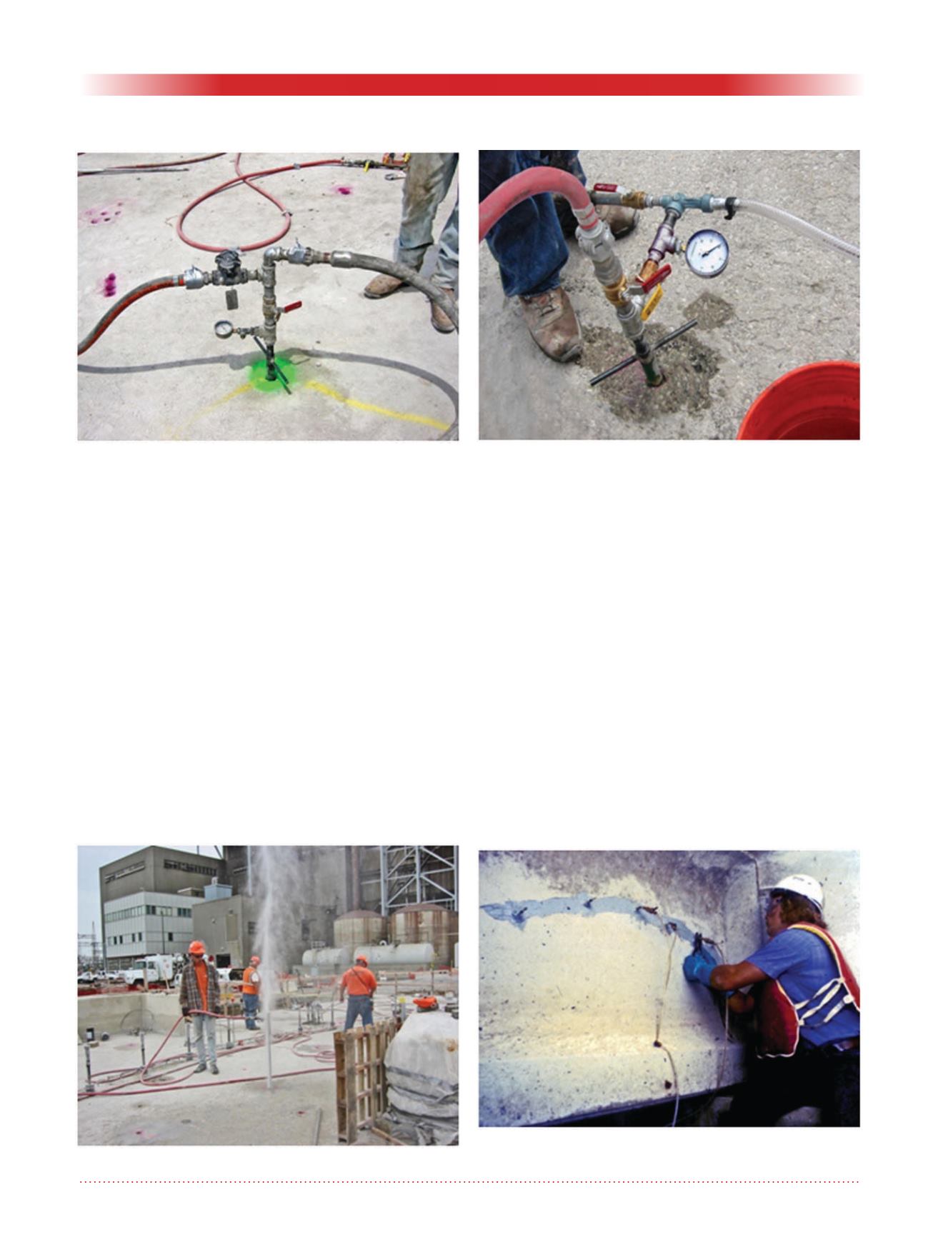
Figure 8. Typical epoxy injection from surface. Cracks are
pre-sealed and operation can be quite neat.
Figure 5. Typical grouting header for circulating injection
system. Supply hose on right, return on left. Valve above
gauge controls injection rate.
Figure 6. Vacuum grouting header. Valved hose top left
is compressed air entering venturi ejector, white hose
on right carries away spent air. Upon sufficient vacuum,
valves are turned from vacuum to grout.


