Geotechnical News • March 2017
37
GEOTECHNICAL INSTRUMENTATION NEWS
the telescope with as small a chance of
ambiguity as possible. Some examples
of these are: paint marks already on
structures and buildings, flat bolts, ink
marks, nail heads, imperfections in
color or marks on bricks and masonry.
Keep in mind that the points may have
to be read during rainy periods so they
should also be visible when wet.
When the initial readings are taken, it
is important to keep in mind that the
geometry used for the initial readings
has to be repeatable going forward.
Large changes in the geometry can
introduce significant ambiguity into
the readings, causing them to become
suspect. Bad data are worse than no
data. Taking the initial and subsequent
readings from a safe, stable and secure
location is strongly advised. With a
little bit of planning and forethought,
it is possible to take accurate and
precise readings from a pre-planned
location(s).
Accuracy and precision
Accuracy is the truthfulness of the
targets location while precision is the
repeatability of measurements to the
same point each time it is measured.
One of the best ways to guarantee
precise results is to use the same
geometry, instrument and operator for
all of the readings. While this is not
always possible in reality, using the
same geometry as much as possible
is one of the most important steps to
follow. While MRTS instruments can
measure to inaccessible locations, it
can be hard to know what happens to
the laser as it travels to and from the
monitoring point or even if it is hit-
ting the right point. Measuring to the
wrong type of surface, not understand-
ing the properties of the laser and how
it is affected by atmospheric condi-
tions and the impact of those condi-
tions on the measurements all have
varying effects. It is also important
to understand what the instrument is
capable of and under what conditions
it operates at its best.
Measurement on two faces
Using the instrument in both faces
will control any calibration errors in
the instrument and is needed for the
accuracy it provides for MRTS read-
ings. By taking readings on both faces
of the instrument multiple times then
averaging the initial measurements of
the controls and the monitoring points
the measurements can be kept within
a tolerable range as long as the correct
procedures are followed. If large dif-
ferences are noted between readings
on either face of the instrument then a
change in geometry to a more perpen-
dicular location is recommended.
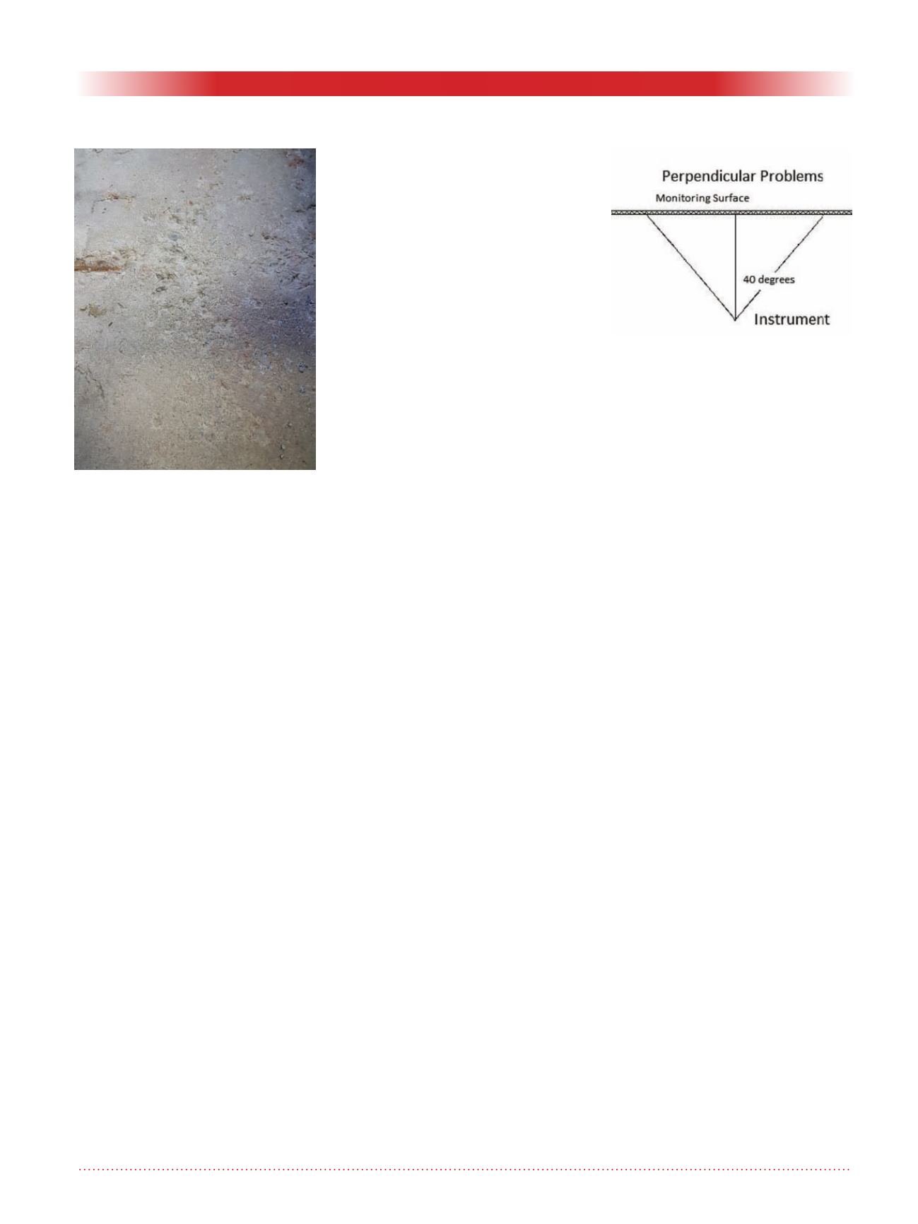
Perpendicularity
By keeping measurement angles
within an 80 degree range as much as
possible, the laser will return an accu-
rate and precise measurement of the
location of the point. A way to think
of this is to stay as perpendicular to as
many monitoring points as is pos-
sible. Any monitoring or control point
should be within 40 degrees of the
perpendicular for the most consistent
and accurate readings. Figure 2 shows
a graphical representation of perpen-
dicularity.
Precise mode versus reflector-
less mode experiment
The same geometry is used for each
set of readings along with the same
operator and instrument. All of the
points being monitored were re-
initialised in both precise and MRTS
mode with the MRTS points also
being read on two faces. Precise Mode
is the method used when reflective
targets are available; however, the
laser is subject to deflection when
objects are within close proximity
of its line of flight. (Approx. 50mm)
Reflectorless mode uses the changes in
the phase shift as one way to calculate
positons while also using the time of
flight method for calculations. During
the monitoring, most of the readings
were taken through temporary fences
which can cause problems in precise
mode, as noticeable deflections occur
when the precise laser travels too
closely to any objects along the line of
sight. Figure 3 shows a colour coded
graph with reds being MRTS mea-
surements and greens being precise
measurements.
Conclusions
When there is a good geometry,
when readings are taken with a high
standard of care and you have the right
instrument, it is a good alternative to
use MRTS monitoring, especially if
traditional methods are difficult or
impossible.
A good geometry is a system of con-
trols installed on at least two axes with
at least five targets spread as evenly as
possible, while staying as perpendicu-
lar to as many points as possible and
not exceeding forty degrees from the
perpendicular when taking measure-
ments.
Figure 2. Shows a graphical repre-
sentation of perpendicularity.
Figure 1. Shows a poor surface for
reflectorless monitoring.


