22
Geotechnical News September 2011
GEOTECHNICAL INSTRUMENTATION NEWS
(RSP) measurements, thanks to a laser
beam aimed directly on the surface.
Nowadays two methods of comput-
ing surface settlement exist:
• The standard method (single points
directly measured by the total sta-
tion)
• The mesh method (treatment of a
number of points to geographically
smooth the results).
We have used both methods ex-
tensively in Europe over the past few
years. Both have advantages and draw-
backs.
This article presents the generalities
of the technique, its potential limita-
tions and requirements, and then briefly
presents two sites where both standard
and mesh methods were used.
How does it Work?
3D monitoring with a RTS consists
of a zero measurement of a network
of points measured in three fixed
directions to be able to follow this
network over time. Preferably the
baseline measurement is performed
previous to any construction work.
A record of the weather conditions
(temperature, pressure and humidity)
and all the factors that could influence
the measurements is very important.
An automatic 3D monitoring system
able to measure surface deformation 24
hours a day is made up of a total station
equipped with a reflectorless distance
meter and a personal computer which
can be operated remotely with specific
software able to drive
the total sta-
tion to predetermined locations of the
points that are to be monitored. We will
refer to this entire system as Reflector-
less Robotic Total Station (RRTS) for
the rest of this article
1
.
1
The commercial name of the whole
system as developed and used by Sol-
data is “CENTAURE”. This name now
appears regularly in articles and speci-
fications, but for the rest of this article
and for future generic use we suggest
the use of the term RRTS for Reflector-
less Robotic Total Stations. As for RTS,
the term RRTS will apply both to the to-
tal station being used and to the whole
system, including all software and data
treatment processes.
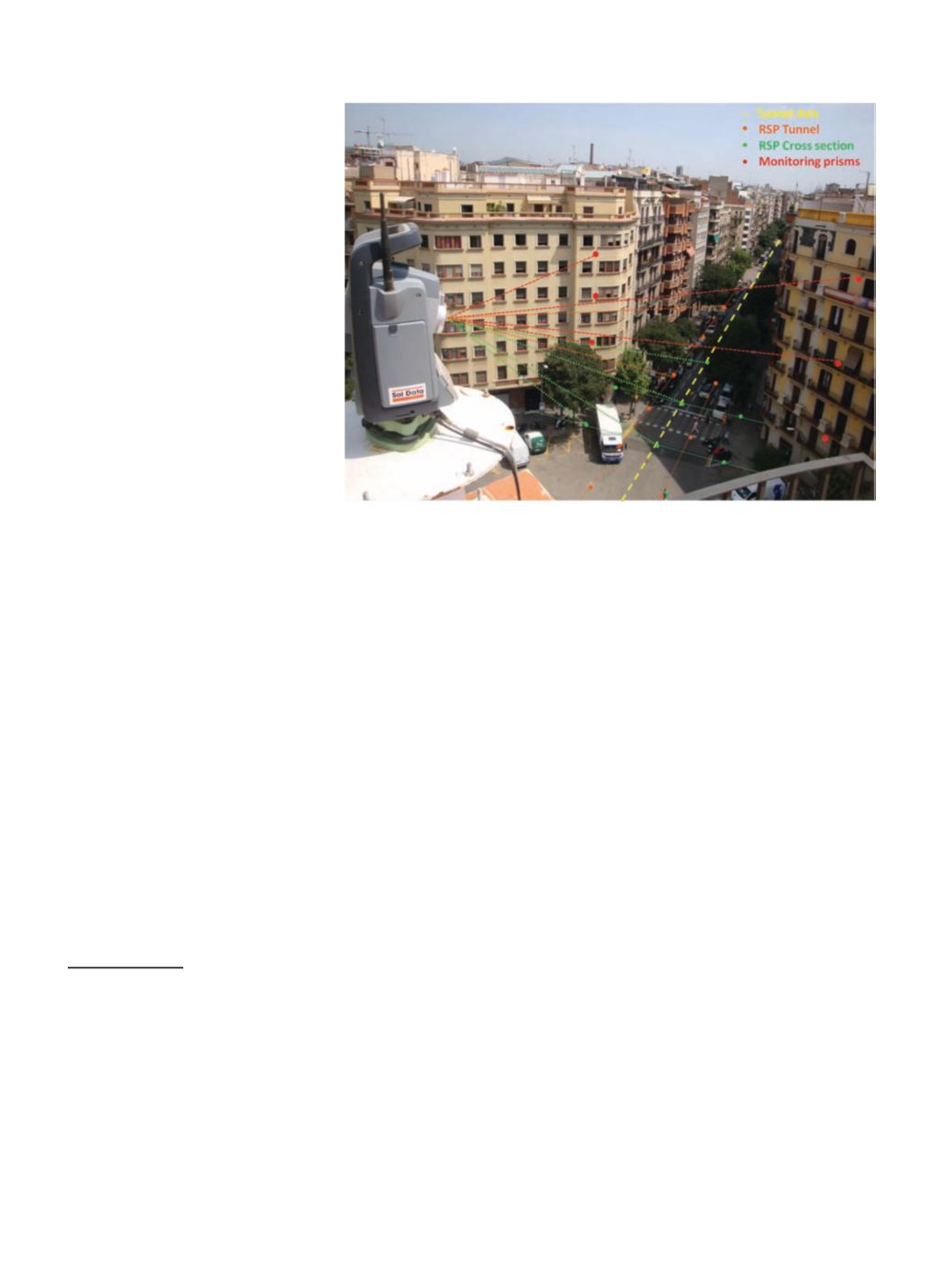
During each monitoring cycle the
instrument sights at two or three groups
of points (see Figure 1):
• RSPs on a flat, homogeneous and
planar surface for which vertical
deformation is to be monitored.
RSPs are not physically marked
and are not physical objects: They
are just a location on the ground at
which the RTS is sighting.
• The stable reference prisms, which
permit computation of the correct
position and the orientation of the
total station.
• If necessary, the same total station
and software can sight monitoring
prisms installed on structures to be
monitored in 3D, the same as for a
standard RTS
On completion of the cycle (typi-
cally 20-40 minutes, depending of the
number of points), the raw data are sent
to the database via Wi-Fi or 3G.
If both the availability and the dis-
tribution of the values meet the quality
criteria then the height of the RSP is
calculated and can be published in real
time via a web-based GIS. Treatments
include sliding statistical analyses of
the data. These methods allow removal
of any accidental errors produced by
the total station, and greatly improve
the precision of the data
This system can also trigger alarms
sent by SMS or e-mail if predetermined
thresholds are exceeded.
System Limitations
References
RRTSs are nearly always installed
inside the area of influence of the work
site where settlements are expected.
The position of the total station and the
associated prisms are computed based
on reference prisms located outside the
area
The adequacy of the whole system
is based on the quality of the reference
prisms. They need to be:
• Well distributed to guarantee the ro-
bustness of the system
• Located in a stable zone outside the
area of influence
• Located at a distance which depends
on the precision required
Range
Depending on the type of total station
used, the range of the distance meter
is limited (typically 60-70m). To
guarantee a good reflection quality of
the laser beam the angle of incidence
on the measured surface is also a
criterion that influences the range of
the measured RSP. Finally the surface
Figure 1. Example of Reflectorless Robotic Total Station (RRTS) installation able to
measure RSPs and prisms.


