46
Geotechnical News •March 2015
GROUNDWATER
An unexpected short-duration warm-up and rainfall event
during winter: ice-clogged drains and damage to a building
Robert P. Chapuis
Context
This is the fourth historical case study
on “groundwater” problems that I
have presented in Geotechnical News.
This unusual case concerns a drainage
system for an industrial building with
distinct sewers for sanitary sewage
water and stormwater. The building
had a nearly flat roof, which is quite
common in industrial areas, probably
because it is cost efficient, requires
less material and provides more room
space than a sloped roof. Also, it is
easier to walk on and inspect.
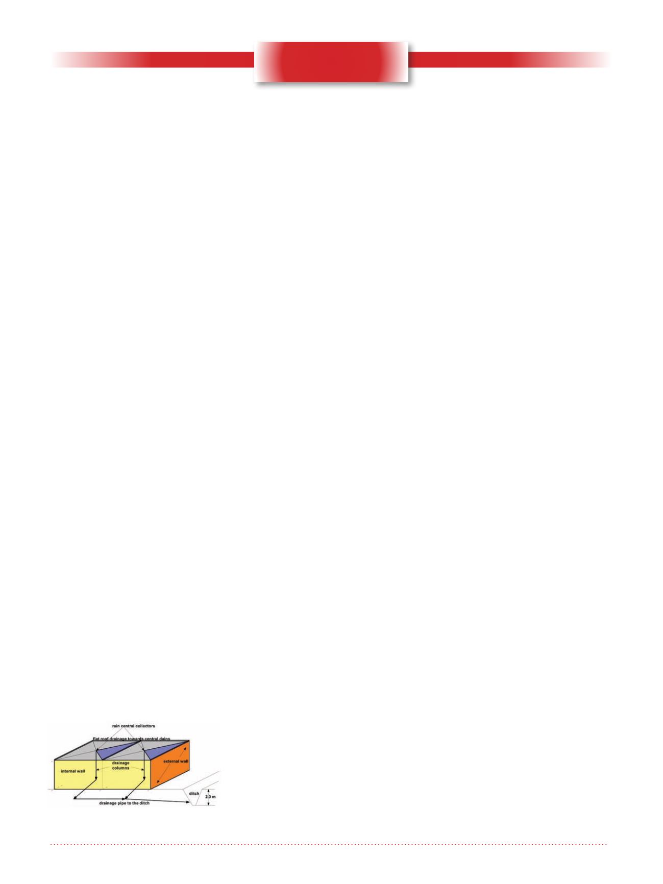
The large roof had several sections,
each with a small slope towards a
central collector, a simple gravity
drainage system which avoids water
ponding. Each drainage column
was located within the heated build-
ing, which avoided the risk of water
freezing and damaging the pipes and
building structure. Each drainage
column discharged rain water and
snowmelt to a sewer pipe, leading the
water towards a ditch about 2 m deep
(Figure 1).
Prior to the event recounted in this
paper, the flat roof was in excellent
condition. There was no water pene-
tration into the underlying decking and
insulation. Each central collector was
protected with a metal screen to avoid
entrance of gravel, airborne debris,
leaves, and wildlife. In addition, the
end of the drain pipe, in the ditch, was
screened to prevent entry and nest-
ing of wildlife, which could cause
clogging. Therefore, clear precautions
had been taken to have a rodent-free
and snake-free building, to avoid pipe
clogging and rodent damage within
the building.
The event
The event which caused damage
occurred in the middle of winter, when
one day, the air temperature rapidly
increased from -15
º
C to a few degrees
above freezing, and stayed above 0ºC
for only 2-3 days. This rapid but short
warm-up also brought a few centi-
metres of rain, which caused some
additional snow to melt, clearly visible
in the parking lot. However, nobody
paid attention to what was happening
on the flat roof, which had to drain
several cubic meters of rain and melt-
ing snow.
Inside the building, some time has
passed before it was realized that
water had started spurting from the
joints of the vertical drainage columns,
damaging the building and some
stored goods. The spurting water was
clear, cold and under pressure. An
employee climbed onto the roof and
saw standing water in each flat divi-
sion. The vertical drainage columns
were made with plastic pipe sec-
tions simply fitting together (no glue,
no welding): this system was quite
frequently used for vertical drainage
pipes, but it cannot resist water under
pressure.
Investigation and repair
The investigation for this case was
quite simple. There were pools of
standing water on the roof. Water was
supposed to fall freely through the
vertical drainage columns but this was
not the case. Water could flow from
the roof into the vertical drainage col-
umns where it was under pressure, but
it was squirting out by the pipe joints
inside the building. Therefore, there
must have been some clogging in the
underground drainage system.
An inspection of the drain pipe outlet
in the ditch revealed that the pipe was
blocked by a long cylinder of ice. Dur-
ing winter, a small amount of water
had started to freeze close to the pipe
outlet, and additional water reaching
this ice became gradually frozen, due
to cold air entering the drain pipe.
As a result, an ice “dam”, made with
a long ice plug, was formed which
blocked water behind it. In previous
winters, there has been no sudden
warm-up, and slow melting of the ice
plug allowed water to reach the ditch.
Unfortunately, during the rapid but
short warm-up in this case, the under-
ground ice plug, insulated from the
warm outside air, did not melt, which
caused damage inside the building.
In order to counteract the possibly
dangerous consequences of a fast
warm-up, a few meters of electric
de-icing (heating) cable were subse-
quently installed in the end part of the
drain pipe, near its outlet. The cable
was similar to those used for keeping
rain gutters free of ice during cold
weather. The heating cable operation
was controlled by a device which
checked the temperature around the
cable, in order to prevent future freez-
ing of water within the drain pipe.
Figure 1. Sketch of the building and
its stormwater drainage system.


