Geotechnical News • September 2016
25
GEOSYNTHETICS
construction of a new earthfill dam
located immediately downstream of
the original hydraulic fill dam (Hart-
ford and Lou, 1994).
Spillway structure rehabilitation
The original concrete-lined spillway
of the Alouette Dam was built in 1926,
with control gates and an overflow
weir, in order to carry flood water
around the earthfill dam and safely
discharge it below the downstream
toe. The elevation drop between
the spillway crest and the Alouette
River was accommodated by an ogee
structure at the end of the spillway: it
was founded directly on the excavated
ground and incorporated a concrete
cut-off toe wall on all three sides.
Erosion protection was afforded by
submerging the discharge section at
the end of the ogee structure, thereby
inducing a hydraulic jump in the
backwater pool, which acts to dis-
sipate energy from the flow of water
(Carpenter, 1927). Further erosion
protection was afforded by a concrete
slab that extended beyond the toe wall,
and by a transition blanket of riprap
along the rise of the channel through
which discharge over the spillway was
returned to the Alouette River. The
spillway was partially rebuilt in 1955
following flood damage (Brown and
Nielson, 1992), and further improved
in 1961, 1983 and 1985 before under-
going a major rehabilitation in 1992
(see Fig. 1).
The “Alouette Dam – 1992 Spillway
Rehabilitation Project” was under-
taken to accommodate a revision to
the design extreme flood magnitude.
Additionally, it was undertaken to
address some observed deficiencies
that had been identified through engi-
neering inspection, including erosion
and undermining of the spillway foun-
dation, as well as deterioration of the
original concrete. Erosion beneath the
spillway was attributed to no provision
being made, at the time of original
construction, for under-drainage
between the spillway and its founda-
tion. The rehabilitation works included
placing a new spillway gate, replacing
the original portions of the spillway
channel, and constructing a new still-
ing basin. Importantly, the rehabilita-
tion work included filter and drainage
provisions underneath the spillway
channel that were intended to prevent
uplift of the slabs during major floods
due to potential large fluctuations in
water pressure during flood routing.
The safe, long-term operation of the
spillway is governed by the capacity
of the under-drain to collect, depres-
surize and remove any groundwater
that seeps into it from the founda-
tion soil. Further, it must collect and
remove any channel flow that enters
it through the concrete liner during
a period of spillway use. In order to
provide for this design function, the
drainage system must be protected
against ingress of the foundation soil
on which it rests. Accordingly, a filter
was placed between the foundation
soil and drainage layer.
The configuration of the drainage
system differs along the length of the
spillway. Where possible, such as
the spillway invert, granular filters
and drains were used. A total of three
combinations of materials were used
in construction: (i) a granular filter and
granular drain, (ii) a geotextile filter
and granular drain, and (iii) a geo-
textile filter and a geosynthetic drain.
More specifically, a granular filter and
drain was specified in contact with the
base of the spillway channel where the
slope is relatively flat. A combination
of geotextile filter and granular drain
was used on the sloping section of the
spillway base. On the steeply inclined
sidewalls of the spillway channel,
the specification required a combina-
tion of geotextile filter overlain by a
moulded plastic sheet-drain of single
cuspate construction (see Fig. 2). The
resulting geocomposite filter-drain
was custom-designed and assembled
on site: several off-the-shelf pre-
assembled products were available at
the time, but were deemed unsuitable
for this application. The sidewalls
were excavated at an ngle of approxi-
mately 1.5H:1V over a length of 170
m on one side, and 50 m on the other
side, of the spillway channel. The
combination of geosynthetic filter and
drain was specified for the sidewalls
because it was expected the steep cut
would present a significant chal-
lenge for economic placement, and
satisfactory compaction, of a granular
material filter and drain. Further, there
was concern that heavy rainfall might
Figure 1. General view.
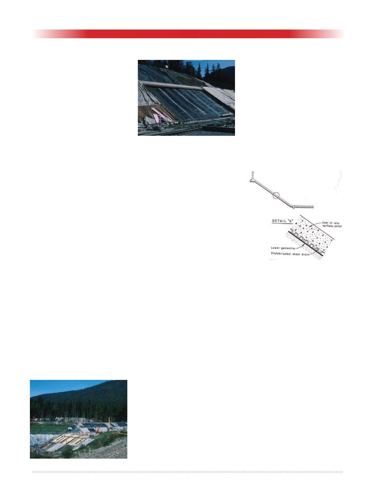
Figure 2. Configuration of the
geotextile filter and sheet drain.
Figure 1b. Inclined sidewall of the
spillway channel.


