36
Geotechnical News • September 2017
GROUNDWATER
Borehole drilling, grout recipes
and piezometer installation
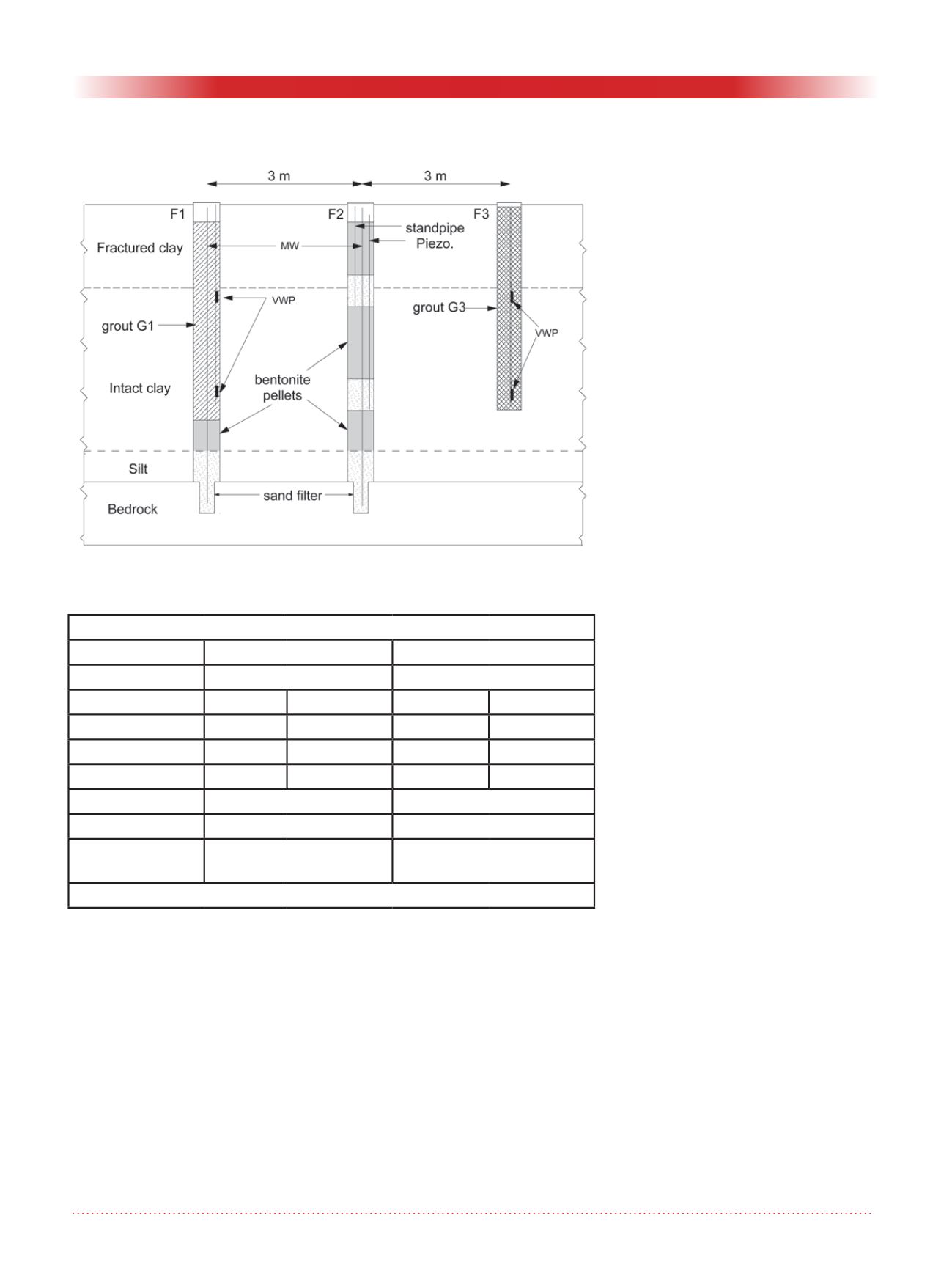
Boreholes F1, F2 and F3 were drilled
in October 2016 using wash boring,
with a flush-joint casing of diameter
114 mm. The boreholes are spaced
3 m apart. Borehole F3 was drilled
to the lower third of the clay layer to
a depth of 12.5 m from the ground
surface while boreholes F1 and F2
were drilled into the bedrock down to
a depth of 22 m. The clay layer was
sampled using thin-walled tube sam-
plers (3”) at 1.5-m intervals. Figure 2
shows a cross-section of the boreholes
F1, F2 and F3. Two monitoring wells
(MWs) were installed in F1 and F2.
The MWs’ intake zones were located
at the interface with the fractured
bedrock and silty layers. In each bore-
hole, two multilevel piezometers were
installed approximately at the lower
and upper third of the clay layer. The
multilevel piezometers monitor pore
pressure fluctuations within the clay
layer. Boreholes F1 and F3 include
two vibrating wire piezometers
(VWPs), which were fully grouted at
depths of 6.1 and 12.2 m below the
ground surface. Borehole F2 contains
two standpipe piezometers with a sand
filter around their screen. The center
of the intake zones for the standpipe
piezometers was located at the same
depth as the VWPs (Fig. 2).
The vibrating wire piezometers were
calibrated before the installation.
The piezometers were kept under
water until their installation. Once
the boreholes were drilled, the VWPs
were attached to a ¾-inch grout pipe,
which was lowered into the borehole
to the appropriate depth. After having
positioned the piezometer assembly
in the borehole, grouting was started
from the bottom up.
Two grout recipes were used to seal
the VWPs in boreholes F1 and F3.
The grout for F3, later referred to as
G3, corresponds to the grout recipe
suggested by Mikkelsen (2002). The
weight proportions were 6.5 parts
water: 1 part cement: 0.4 parts ben-
tonite. Mikkelsen (2002) suggested
adding more bentonite to this recipe
for viscosity adjustments. Bentonite
was not added in this case to obtain
the properties for the exact recipe. A
new grout recipe (G1) was designed
for borehole F1 with a higher benton-
ite content. The weight proportions
for the new recipe were 5 parts water:
1 part cement: 1.2 parts bentonite.
The higher amount of bentonite made
the grout more viscous. A viscous
grout does not easily flow into nar-
row spaces, for example between
the piezometer cord and grout pipe.
Therefore, a liquid and chloride free
superplasticizer (SP) was added in rec-
ipe G1 in order to increase the grout
flowability. The concentration of SP
was about 2.0% of the solid weight.
The laboratory values for the Marsh
funnel viscosity were 55 s and 29 s
respectively for grouts G1 and G3.
All materials used in this work were
produced in Canada. The cement was
general use (GU) cement, and the
sodium bentonite (Opta Minerals) was
a powder. Tap water from the city of
Figure 2: Cross-section of the piezometer installations.
Table 1: Grout recipes, permeability and compressibility for grouts G1 and G3
Borehole F1
Borehole F3
Grout
G1
G3
Material
M (kg)
Ratio
M (kg)
Ratio
Water
120
5
120
6.5
Cement
24
1
18.5
1
Bentonite
28
1.2
7.5
0.4
SP
1
(% of solid)
2.0
none
permeability (m/s)
6.1×10
-9
1.2×10
-6
compressibility
(kPa
-1
)
4.15×10
-5
5.9×10
-5
1
SP = Superplasticizer


