30
Geotechnical News • March 2018
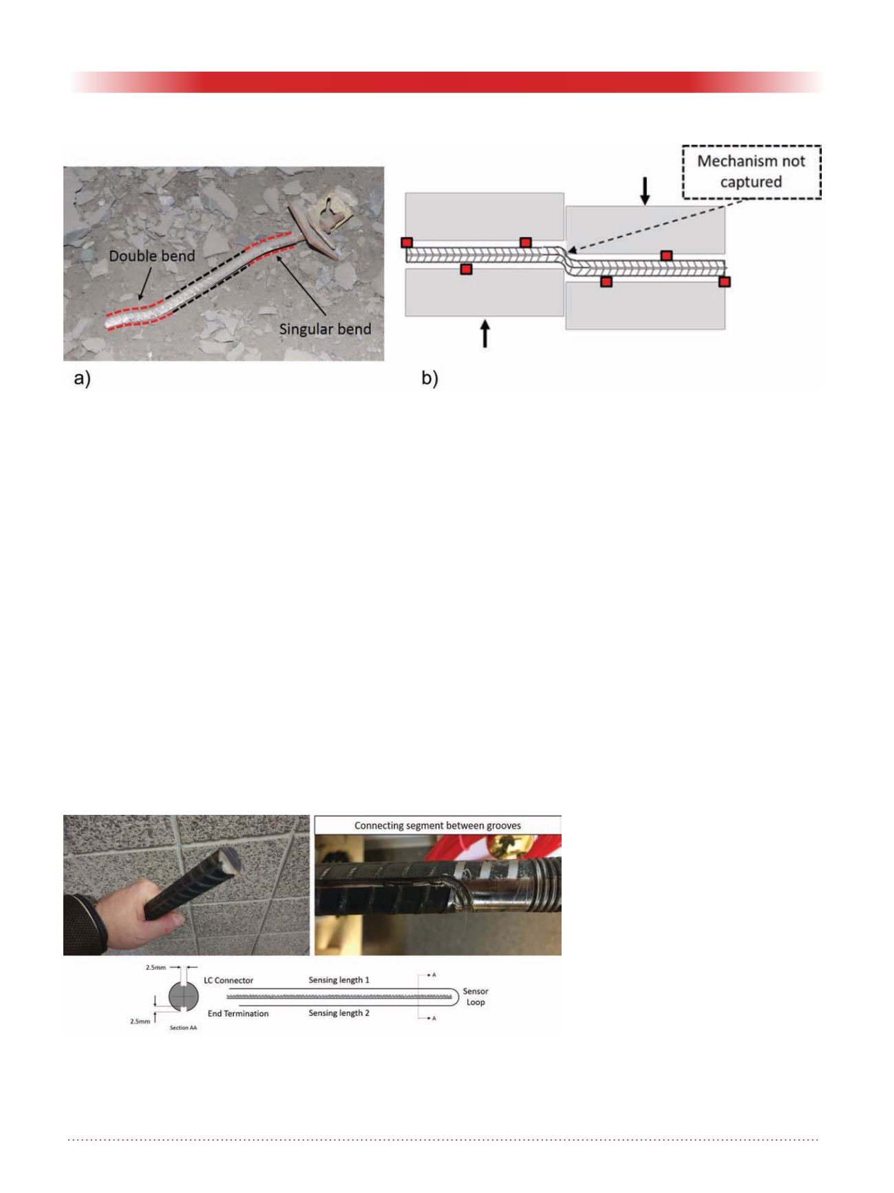
In order to test the technology and
methodology developed, No. 6 Grade
60 rebars were prepared by instru-
menting them with a fiber optic. Steel
bars were modified with 2.5 mm
by 2.5 mm diametrically opposing
grooves as shown in Figure 3.
Performance? Lessons learned?
Selected laboratory testing and
results
To date, many configurations of test-
ing that include axial, bending, and
shear testing have been conducted
utilizing multiple support elements.
These support elements were tested as
unique specimens as well as grouted
within concrete (rock) samples. The
support tested in the laboratory to date
includes: Rebar (rock bolts), D-bolts,
Cable bolts, Spiles and, Forepoles.
Each sample preparation has its own
unique challenges in terms of fitting
the fiber optics in conjunction with a
particular support element. In Figure
4 below, one can see selected results
from the laboratory testing that has
been conducted as part of this line
of research. Figure 4a depicts results
from an axial pullout test while Figure
4b depicts results from a 2-way shear
test.
Field trials
As with any technology of this nature,
it is encouraging to obtain excellent
results within the controlled environ-
ment of the laboratory. The question
now becomes how this technology can
be employed in the harsh conditions
associated with the field while limit-
ing its impact on operations. To date,
multiple successful field experiments
have been conducted at 3 separate
locations around the world. The
authors are also in contact with other
interested global parties who have
shown an interest in employing such a
technique within their operations.
Below (Figure 5) are relevant photos
from the in-situ installation of the
fiber optic technology within support
elements that were designed by the
authors. The data amassed in the field
to date is of excellent quality, how-
ever, at the time of publication these
results had not been authorized for
release. None-the-less, it is extremely
encouraging that the technology devel-
oped and tested at RMC is functioning
as expected within the austere field
site conditions with no real interrup-
tion to tunnelling or mining opera-
tions. It should also be noted that a
unique fiber optic instrumentation
solution must be determined for each
type of ground support element; this
is a non-trivial undertaking due to the
unique requirements and installation
procedures associated with each type
of support and site.
COMPUTING IN GEOTECHNICAL ENGINEERING
From the GS Board
Figure 3. Photos and schematic depicting the grooves that were created
during specimen peparation and the outfitting of the optical fiber with details
of optical fiber groove; fiber was looped around one end of the rebar
specimen providing continuous strain monitoring along two sides of the
sample.
Figure 2. a) Permanently deformed bolt from an active mine site that indicates that the bolt has undergone lateral
deformation and b) Deformed rebar element with sensors (red locations) that are too sparsely arranged in order to
capture the local phenomenon.


