Geotechnical News • March 2018
31
Conclusions
The distributed optical strain sensing
technique has been verified as a novel
monitoring and geotechnical tool for
capturing the performance of ground
support members used in underground
projects. The sensitive spatial resolu-
tion allows a continuous strain profile
to be measured, overcoming the
limitations of conventional, discrete
strain measuring techniques, which
in most cases will not fully capture
the geomechanical behaviour of the
support, especially when considering
localized complexities. The results of
using this instrumentation with ground
support elements in the laboratory and
the field have provided confidence
for using and improving upon such a
technique within the field. In addition,
the optical technique can be realized
as a novel tool with the capability to
“see” and “sense” into the ground
ahead of the working face, allowing
the engineer to react and make adjust-
ments to the support and excavation
process in response to future ground
conditions. As a monitoring solution,
DOS provides unparalleled informa-
tion concerning the behaviour and
the interaction between the ground
medium and the support elements
which can be back-analyzed for pre-
dictive numerical model methods and
ultimately support design optimization
The authors wish to acknowledge the
support of the following industrial as
well as governmental sponsors: Natu-
ral Sciences and Engineering Council
of Canada (NSERC), the Canadian
Department of National Defence,
Yield Point Inc., The Royal Military
College (RMC) Green Team as well
as the very real contributions/roles of
Dr. Mark Diederichs and Dr. Andrew
Hyett.
Nicholas Vlachopoulos
Professor Royal Military College of
Canada (RMCC) within the Civil
Engineering Department and
Director of the RMC Green Team.
Bradley Forbes
PhD Candidate within the
GeoMechanics group of the
Geological Sciences and Geological
Engineering Department at Queens
University.
COMPUTING IN GEOTECHNICAL ENGINEERING
From the GS Board
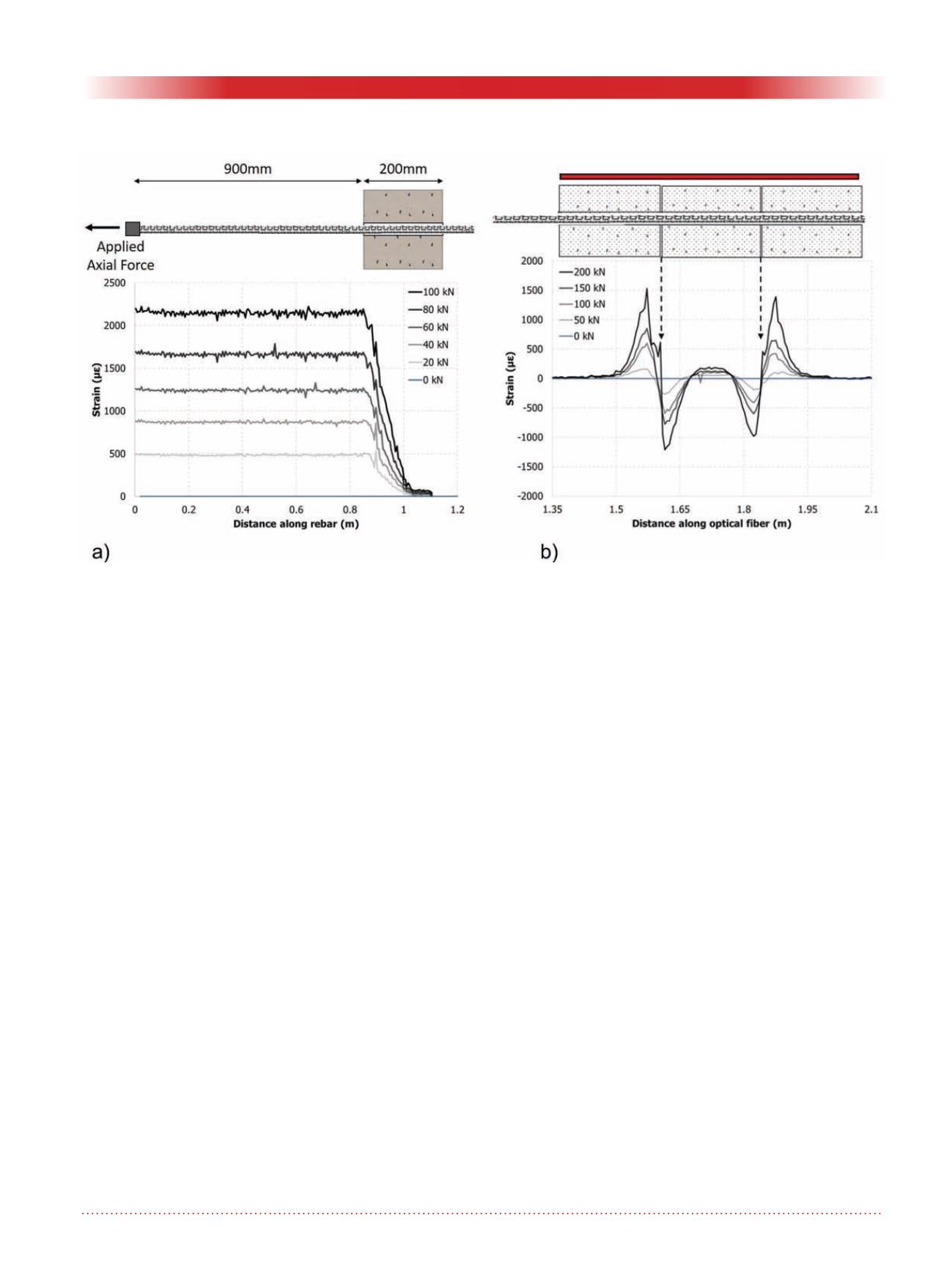
Figure 4. Selected results from a) pullout testing configuration and b) 2-way shear configuration.


