44
Geotechnical News • March 2018
THE GROUT LINE
distribution etc.) as well as dewa-
tering and electrical systems
• Security situation in Northern Iraqi
limits the movement of the grout-
ing staff to the site and within the
site. Increases difficulty to recruit
technical staff for the engineer and
contractor.
• Complicated logistics to move
equipment, tools, consumables and
supplies to project site.
• Procurement of materials, tools
and equipment is difficult due to
current made to order European
approach.
• Change in the control of the area
from the Kurdistan region to
the central government of Iraq
impacted the local work force with
some workers not being able to
cross the check points/border to
reach the site
The need to upgrade the legacy grout-
ing systems to meet the demanding
production needs while concurrently
drilling and grouting holes presented
a significant amount of challenges at
the beginning of the project. Approxi-
mately 1950 holes were planned to be
drilled and grouted to establish a sin-
gle line grout curtain across the entire
3.4 km of the dam. The 1950 holes
account to approximately 250,000 m
of drilling and grouting. Of the 1950
planned holes, about 500 were on the
crest and the remaining were in the
grouting gallery. The depths of the
holes varied between 50m and 150m
with an average depth of 100 m.
The magnitude of the grouting effort
required special infrastructure includ-
ing:
• Construction of 3 grout mixing
plants
• Installation of grouting lines and
electrical cables
• Procurement of nine new drill rigs
• Construction of new electrical, ven-
tilation, communication/internet
and water/wastewater systems
• Procurement and setup of 20 BGUs
and ancillary equipment
• Construction of six new office
buildings and a new repair-mainte-
nance shop
• Construction of a secure base
camp facility to provide living and
working accommodations for the
approximately 1000 people on site
To meet the schedule, drilling and
grouting has been performed 24 hours
per day six days per week. To direct,
control and monitor this large round
the clock operation the Owner speci-
fied state-of-art technology includ-
ing advanced communication and
computer-based monitoring systems,
equipment, grout mixes, drilling and
grouting methodologies.
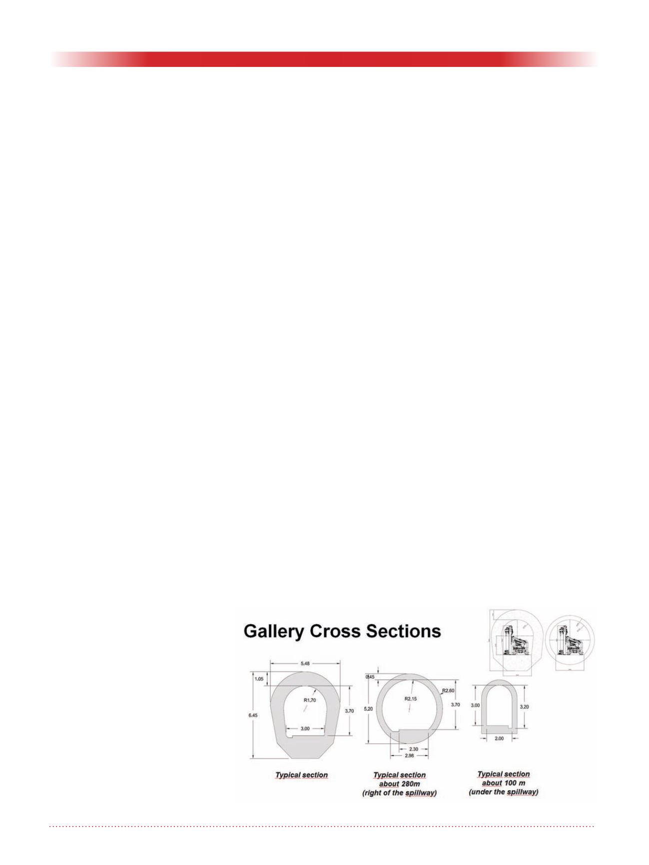
Grouting gallery configuration
The configuration of grouting gal-
lery cross section and profile across
the length of the gallery varies and is
shown in the schematic below (Fig-
ures 4 and 5).
The steep slopes (up to 41%) and
configuration of the gallery cross
section posed a significant challenge
in terms of equipment configuration
and maneuvering requirements. The
grouting units (pumps and dispensing
hoppers) were designed to fit within
the limited space. Customized drill
rigs that can fit within the gallery and
with all terrain capabilities to travel up
and down the slopes were designed for
the job.
Infrastructure upgrade
The infrastructure in the gallery that
was in-place at the beginning of this
task dated from the construction of
the dam. The legacy infrastructure
needed to be replaced in its entirety.
The infrastructure upgrade included
new electrical, water/wastewater,
grout conveyance, grout mixing
plants, communication/internet, light-
ing, ventilation, and concrete delivery
installations (Figures 6 and 7). Details
of the systems are as follows:
• Electrical: Upgrade included
removal of over 3000 m of old
cables and installation of new
cables (170,000 m), cable trays,
transformers and generators to
supply power for the gallery and
crest of the dam.
• Water/wastewater: Over 4500 m of
new pipelines were installed (and
2000 m relocated) to carry fresh
water/wastewater in and out of the
gallery. New submersible pumps
to circulate fresh water through the
3.4 km dam were installed. This
upgrade also included installation
of new sump pumps that carry the
wastewater from the sumps to the
siltation tanks outside the gallery.
• Grout mixing plants: Three per-
manent grout mixing plants that
operate on weight-based batching,
were constructed and positioned
across the length of the dam to
Figure 4. Grouting gallery cross Sections.


