46
Geotechnical News • March 2018
THE GROUT LINE
ing; and Six Soilmec SM-5 and one
Ripamonti Birdie electrical rigs were
purchased for drilling inside the gal-
lery (Figures 8 and 9).
Aside its narrow width, the gallery
presented other limitations to the
mobility of the rigs including steep
ramps, sharp turns at the intersection
with the access galleries, new and
old infrastructure that needed to be
protected and multiple existing rows
of stand pipes. Over 2200 stand pipes,
one for each grout hole, are installed
at the site. The stand pipes extended
four to six inches above the gallery
floor to facilitate the installation of
clamps to secure blow off preventers
and other tools when grouting. While
the protruding stand pipes were neces-
sary they presented a trip hazard and
serious difficulties to the movement
of equipment, tools and supplies.
The Contractor submitted a proposal
to cut the stand pipes flush with the
gallery floor and install insert pipes
with a flush threaded joint at its top
end. The insert would work with a
screwed in extension to connect to the
required tools. The Owner expressed
serious concerns and prior to approval
requested multiple checks and tests to
ensure the inserts and screw extension
could withstand the backpressures
expected and experienced at the site.
Special grouts were designed and
tested to ensure the correct bonding of
the inserts to the existing standpipes,
the inserts were modified with central-
izers, a dedicated crew was trained to
ensure proper installation and a testing
apparatus was configured to test the
pull-out resistance of all installed
inserts. Figure 10 shows the protrud-
ing stand pipes and the completed
inserts.
Given the limited space constraints in
the gallery, hauling the material and
batching the grout mixes adjacent to
the injection hole is not practical. The
grouting system utilized was designed
to prepare a base mix at the mixing
plants outside the gallery and use the
grout conveyance system to bring it
into the gallery in a continuous loop.
Additional conveyance lines con-
vey bentonite slurry and fresh water
through the gallery. The batching and
grouting units located at the injection
holes draw the base mix, bentonite
slurry and water from the conveyance
systems and use localized volumetric
batching to prepare the desired mix
(Figure 11).
The batching and grouting units are
custom designed to operate in the
gallery under high artesian conditions
and with the ability to pump at high
pressures and flow rates. The units are
also automated to communicate with
computer-based monitoring systems
and to be remotely managed by grout-
ing software (Figure 12).
Grouting
Grout Mixes
Grout mix design took into consider-
ation the capacities of the grout pump,
limitations of the grout monitoring
systems, grouting software, convey-
ance systems and weather conditions.
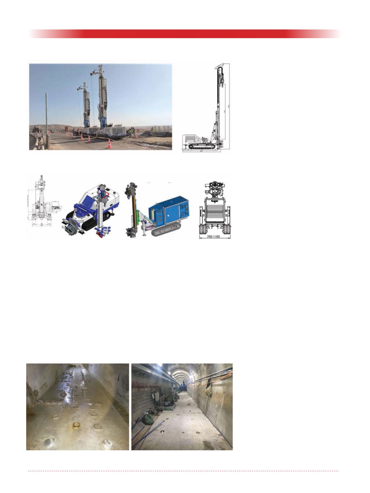
Figure 9. SoilMec SM-5 drill rig (left) and ripamonti birdie E250 (right) drill
rig for gallery operation..
Figure 8. Soilmec SM-16 drill rigs for outdoor operation.
Figure 10. Gallery with legacy Iraqi standpipes (left) and with standpipes cut
flush to surface (right).


