Geotechnical News • March 2019
37
site facilities in order to obtain reliable
evaporation rates. The main differ-
ence between vegetated areas (where
usually the ECV method is used) and
mine sites is that certain areas of the
latter are typically subject to dust
transport that may affect the opti-
cal reader of a gas analyzer, which is
based on a laser beam. Also, despite
the fact that mines are extended areas,
they are usually intervened by struc-
tures or mass accumulation of some
sort that creates aerodynamic interfer-
ences.
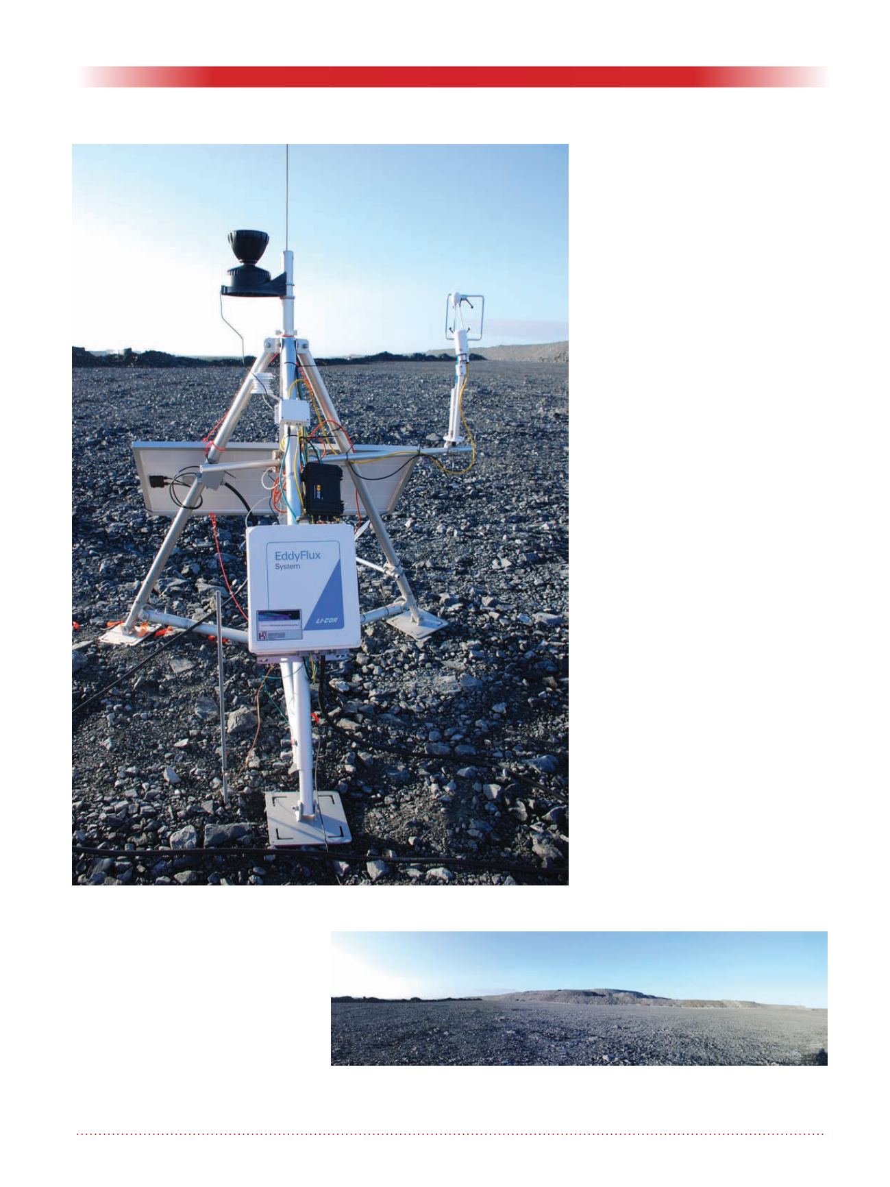
As part of the research project, ECV
instruments have been deployed at
two waste rock dumps located in the
Yukon and Ontario, Canada, during
2018 (see Figure 2).
The present research project aims to
make this technology available to the
mining industry in order to improve
the closure design of waste rock
dumps and the water management
of TSFs. This is a continuation of a
project led by Janeen Ogloza at the
University of Alberta under the direc-
tion of Dr. Wilson in 2017 that focused
on the measurement of evaporation
rates in oil sands tailings ponds. From
that research, we better understood
the difficulties that the aerodynamic
interferences (generated by the dykes
containing the tailings) imposed on
the measurements. Nevertheless, reli-
able evaporation rates were obtained
that ranged between 58 and 76 times
smaller than the potential evaporation
(Ogloza, 2017).
To overcome aerodynamic interfer-
ences, a proper ECV location and
height adjustment considering surface
roughness is fundamental to sample
data that is contained within the avail-
able footprint limits (see Figure 3).
It is expected for the summer of 2019
to continue the deployment of the
ECV instruments at other mine sites
(in particular in TSFs). This would
allow, depending on the positioning
of the ECV instrumentation relative
to the TSF and the predominant wind
Figure 3: Available footprint to perform ECV measurements. Berms and pile
benches present a challenge in terms of aerodynamic interferences. Credit:
Sebastian Fernandez.
Figure 2: ECV used at one of the waste rock dumps studied.
Credit: Sebastian Fernandez
WASTE GEOTECHNICS


