30
Geotechnical News December 2010
Geotechnical Instrumentation News
and quantity of the strain transfer from
the jacket to the fiber, as by far not all
commercially advertised “FO strain
sensing cables” do fulfill this require-
ment sufficiently. In addition, the FO
cable design needs to allow for strip-
ping of the protection layers down to
the fiber itself in order to repair (splice)
the broken fiber.
Several single mode FO cables were
used in this study, ranging from bare
fibers to well-protected prototypes of
tight buffered FO strain sensing cables.
Special attention was given to include
only easy repairable FO cables in our
research. Table 2 gives a brief over-
view of these FO cables.
Defining and Monitoring of
Landslide Boundaries
Motivation
Differential
soil
displacements
initiated by creeping landslides
can cause immense problems by
damaging infrastructure and buildings
in the sliding area. Moreover, special
construction
and
reinforcement
requirements, or even total halt of
construction within a landslide area
may be demanded by local construction
laws. In some cases it is therefore of
crucial importance to determine the
exact position of the boundary between
the landslide and the stable part of the
slope. Geodetic measurements can
identify the boundary on the surface,
but not necessarily with high accuracy.
Inclinometers serve for detection
of the sliding surface, but once an
inclinometer casing is excessively
distorted, a conventional inclinometer
probe can not be inserted and the
inclinometer will no longer produce
results.
New landslide monitoring tech-
niques by means of distributed FO
technology can offer an unprecedented
amount of high quality data at reason-
ably low costs. By performing opti-
cal strain measurements along the FO
cable, the transition zone between the
sliding and the stable parts can be iden-
tified. Several systems to determine
this boundary have been successfully
implemented in field projects on creep-
ing landslides in the area of St. Moritz,
Switzerland, as described below.
Asphalt Road-Embedded FO
Cable
The first system, an asphalt road-
embedded
FO
cable, serves for
the evaluation of
such a boundary
in an urban area.
An instrumented road, which intersects
this boundary, can be seen as a large-
scale strain gauge. The FO cable (of
longitudinal stiffness EA between S06
and P07 in Table 2) was glued at 1m
intervals inside a trench (about 10mm
wide by 70mm deep) cut into asphalt,
with a temperature sensor placed on
top of it. Subsequently, the whole
trench was filled with an elastic cold
sealing compound.
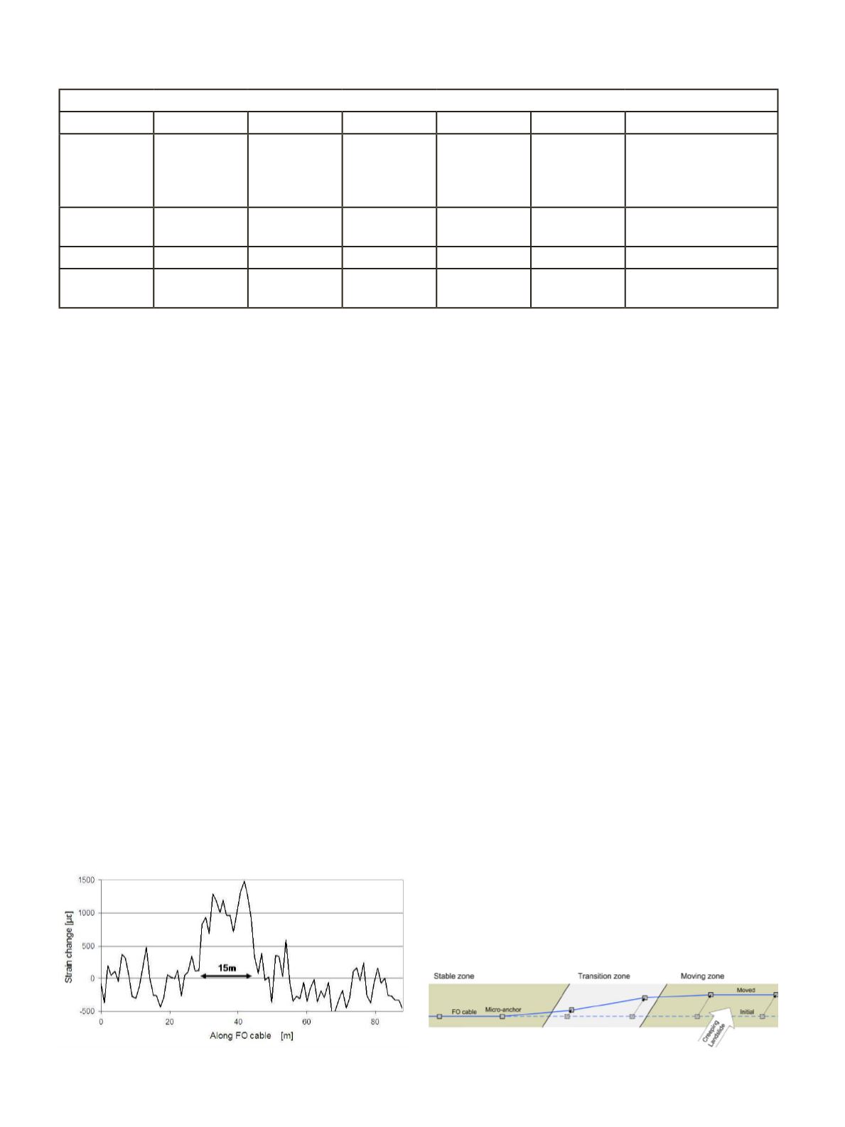
Since 2006 three such road-em-
bedded systems have been integrated
and tested in the field. The differen-
tial strain along a 90m long FO cable
accumulated in a 7 months period is
shown in Figure 1. The transition zone
has been identified as a 15m long sec-
tion and the landslide movement esti-
mated at about 20mm (by multiplying
the measured strain by the length of the
transition zone and assuming that the
FO cable crosses the boundary at 45°
angle). This was later independently
verified by geodetical data. Good re-
peatability of measurements was con-
firmed by installing another FO cable
at the same location.
Soil-Embedded “ Micro-Anchor”
-FO Cable System
For the boundary identification
in an area where no road or other
infrastructure exists, to which the
FO cable could be attached, a soil-
embedded “ micro-anchor” -FO cable
Table 2: FO cables used
BSM
TSM
S06
S08
P07
S09
M07
Bare fiber
Tight buffered
fiber
Heat shrink
tube protected
TSM
Polyurethane
protected
cable
Polyamide
protected
cable
Polyamide
& metal
protected
cable
Metal protected cable
0.25mm
diameter
0.9mm
diameter
2mm by 3mm 2.8mm
diameter
1.6mm
diameter
3.2mm
diameter
0.9mm diameter
EA = 0.9kN EA = 0.9kN EA = 2kN EA = 2.5kN EA = 3kN EA = 50kN EA = 70kN
Commercial
product
Commercial
product
Custom
produced
Prototype
Prototype
Prototype
Prototype
Figure 2. The “micro-anchor” - FO cable system.
Figure 1. Strain data along a road-embedded FO cable.


