Geotechnical News December 2010
31
Geotechnical Instrumentation News
system has been developed (Figure 2).
The principle of this second system
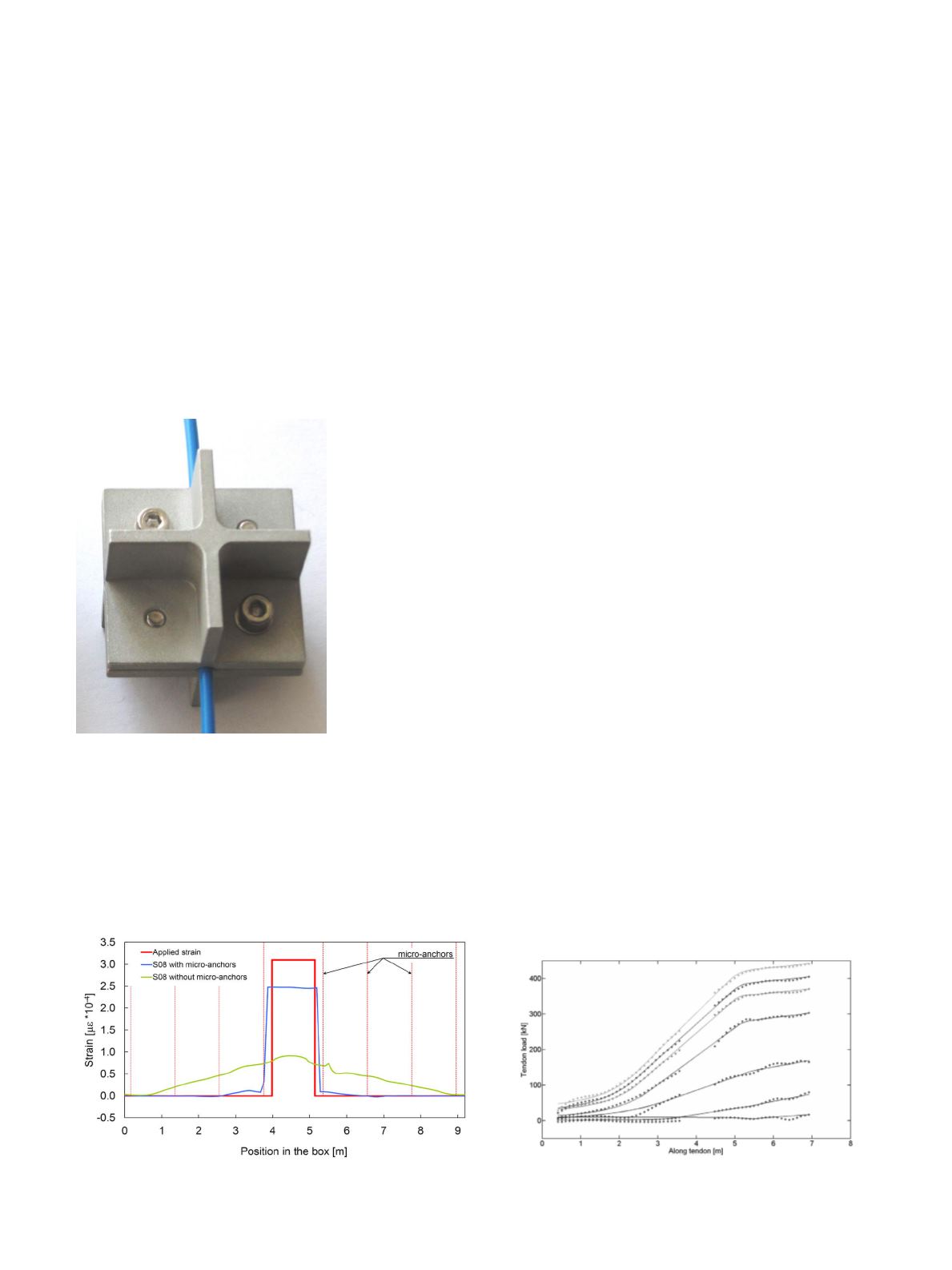
is that a FO cable fixed to “micro-
anchors” buried in soil experiences the
same movement than the soil around
it. The “micro-anchor” (Figure 3)
consists of three perpendicular planes
in order to provide bearing resistance
in all directions and to act as a three
dimensional “dead” anchor. The anchor
size (side length of 40mm, 60mm
or 80mm, respectively) is chosen as
a function of the anchor depth and
the stiffness of the chosen FO cable
(preferably S08 and S09, Table 2).
Large scale laboratory testing of the
system in a 9m long shear box proved
the system to be very efficient. Com-
pared with data obtained by FO cables
buried without anchors and FO cables
embedded into geotextiles, this system
is significantly more sensitive. Figure
4 shows data from such a test of a FO
cable without anchors and a FO cable
with anchors. Additionally to the labo-
ratory testing, an 80m long system has
been successfully installed in a field
project in St. Moritz. The temporal
change in the measured strain incre-
ments correlates well with the indepen-
dent geodetical and inclinometer mea-
surements in this location.
Reactivation of Old
Inclinometer Casings
The third monitoring system takes
advantage of old, out-of-service,
inclinometer casings. In order to
continue using such casings, a FO
cable (P07 or S08, Table 2) is placed
inside and the casing is filled with
cement-bentonite grout. The current
sliding surface can then be identified
and displacements on this surface
back-calculated. Installation of such a
system on site in 2008 allowed for the
sliding surface to be detected within
three months.
Applications in Ground Anchors
Motivation
The determination and monitoring
of the stress distribution along the
grouted section of a loaded ground
anchor tendon is essential for the
understanding of its bearing behavior.
Strain along anchor tendons is normally
measured at distinctive points by
various sensors, such as conventional
strain gauges and more recently, fiber
Bragg gratings. Other approaches are
based on elongation measurements
in a very limited amount of tendon
sections, such as the regularly-used
commercially available monitoring
anchors that offer strain readings in up
to four sections.
A novel monitoring ground anchor
using embedded FO cables allows for
continuous strain assessment along the
anchor tendon, and thus provide a pow-
erful tool for calculating the load distri-
bution in the anchor tendon, which is of
interest to the geotechnical community,
as other reliable methods are rare.
Design and Installation
The monitoring anchor is built of a
tendon consisting of a hollow steel
bar with a threaded outer surface of
35mm diameter. As the integration of
FO cables is one of the key factors,
two different integration methods were
tested: integration in grooves machined
on the outside of the tendon at 180
degrees to each other and internally
in the hollow of the tendon. In the
groove (1mm wide, 2mm deep), the
FO cables (BSM, TSM & P07) are
directly glued to the tendon. In internal
integration, the FO cables (P07, S08
& M07) are placed inside the hollow
center of the tendon later filled with a
low viscosity injection resin. In 2009,
such an 8m long monitoring anchor has
been installed in a drillhole with a fixed
anchor length of 5.75m (grouted). The
anchor was integrated into a sheet pile
wall supporting an excavation pit.
Monitoring
During anchor pullout testing, the
anchorwasloadedinstagesupto470kN,
almost reaching its ultimate bearing
capacity. BOTDA measurements were
taken at each loading stage recording
Figure 4. Strain measurements in a shear box obtained by a
FO cable only and the “micro-anchor” - FO cable system.
Figure 5. Monitoring ground anchor: load distribution from
FO measurements for selected load steps.
Figure 3. The “micro-anchor”.


