28
Geotechnical News • September 2012
GROUNDWATER
Check the elevations of monitoring wells:
They can change with time
Robert P. Chapuis
This paper presents an example of
how monitoring well (MW) eleva-
tions can change over time. The MWs
were installed in stratified sediments
at Sorel, about 100 km north-east of
Montreal, on the south shore of the
St-Lawrence River. Polytechnique
Montreal has been using the site for
student field training in groundwater
engineering and geophysics over the
past decade. The site is part of a large
wastewater treatment facility, includ-
ing lagoons of 320000 m
2
, which were
made watertight using sand-bentonite
liners. The fully fenced site is under
the surveillance of wastewater operat-
ing teams. The site is located on a
large floodplain at the confluence of
the Richelieu and St-Lawrence Rivers.
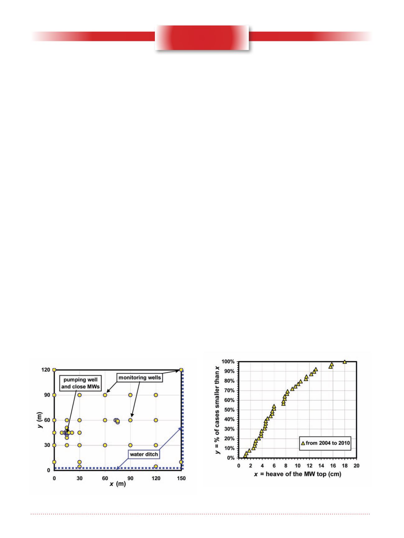
The surface of the training site is
about 150 m x 150 m, and is nearly
flat. Two sides of the site have a drain-
age ditch, with water flowing most of
the year (Fig. 1). The MW positions
(one per borehole) appear in Fig. 1.
The mean spacing between BHs is 30
m, except in the pumping well area
where many MWs were installed close
to the pumping well for measuring
the groundwater drawdown in four
directions.
Boreholes were advanced using a
flush-joint NW casing, which was
driven into the ground. The casing
inside was washed using clear water
and upward water flow. Soil samples
were taken using a standard split
spoon. The stratigraphy includes an
upper part of about 5.25 m made of
many layers of fine sand (deposited
in low velocity water) and silty clay
(deposited in ponds), and a deeper part
of silty clay. A more complete descrip-
tion is given in Dallaire (2004).
The MWs are made of flush-joint PVC
pipes, of 1.5 inch in internal diameter.
Plastic slotted screens are 46-cm long,
most of which were installed at depths
between about 4.0 and 5.25 m, usually
in a fine sand semi-confined aquifer.
The annular space between the casing
and the MW pipe, above the filter sand
(1.0 to 1.5 m high on average), was
sealed using bentonite pellets, except
for its upper part, near the surface,
which was filled with fine crushed
rock.
A very limited budget was avail-
able for the site investigation and
instrumentation. As a result, there
are no security steel casings around
the plastic MWs. The water table is
close to, or at the ground surface at
Figure 1. The Sorel experimental site.
Figure 2. Measured heave for the top of monitoring wells,
between 2004 and 2010.


