Geotechnical News • September 2012
35
GEOTECHNICAL INSTRUMENTATION NEWS
GEO-INTEREST
New meshing algorithm
Alfredo Arenas
Introduction
Three dimensional advanced numeri-
cal analyses are becoming more com-
mon in daily engineering practice. The
first step in a 3D numerical analysis is
to set up the mesh, thus closely repre-
senting the physical problem. This is
not always an easy task and frequently
requires the help of meshing tools.
There are many meshing tools capable
of creating advanced models, but most
of them lack of important features
essential for static and dynamic analy-
sis.
The present article presents the devel-
opment of a meshing tool that over-
comes many of these limitations.
The limitations of currently readily
available meshing tools summarized
below.
• They are sold separately from the
main core software. Although,
they are a powerful and flexible
platform for creating models, they
can cost as much as US $12,000.
• They are complex to use and may
require several steps to create the
mesh.
• They produce non-structured
meshes. Several programs use
tetrahedral elements because they
can be adapted to various shapes
by adjusting the orientation and
size of the element, but at the cost
of producing chaotic unstructured
meshes. This often leads to having
very small elements at places were
the geometry is complex and tight.
• They do not use transitioning
schemes. The majority of these
programs when creating structured
meshes, use a constant number of
elements in the elevation direction,
thus when the meshing process
reaches a convex shape, a concen-
tration of elements is inevitable.
• They avoid the use of wedged-type
elements, because they are hard
to incorporate in the model, but a
wedge-type form is necessary, for
example in the case of the toe of
an embankment dam.
• They use non-balanced meshes.
Most of the time the creation of
un-structured meshes produce
unbalanced meshes, i.e. a very
small ratio of the smallest element
volume to the largest element vol-
ume in the mesh, thus leading to a
large computing time.
• They require large computer
processing time. Many algorithms
take hours in developing the 3D
mesh, making them impracticable
when comparing different geomet-
ric shapes.
In the light of these limitations, it
was decided to develop a meshing
tool that would be easy to use, creates
semi-structured meshes, includes
transitioning schemes, uses wedge
shapes, produces balanced meshes and
requires short processing time.
Initial definitions
A careful selection of the base ele-
ment is required to create a meshing
tool capable of reproducing complex
geometries such as irregular surface
topography. The element has to allow
mobility in the model space and be
oriented in any direction. The most
common and basic shapes are the
triangle, square and rectangle. Of
these, the triangle is the most flexible
(adaptable). The triangle can perfectly
match all of the three corners to an
irregular surface without altering the
face planarity and it can be extruded to
form a triangular prism.
The 3D meshing tools
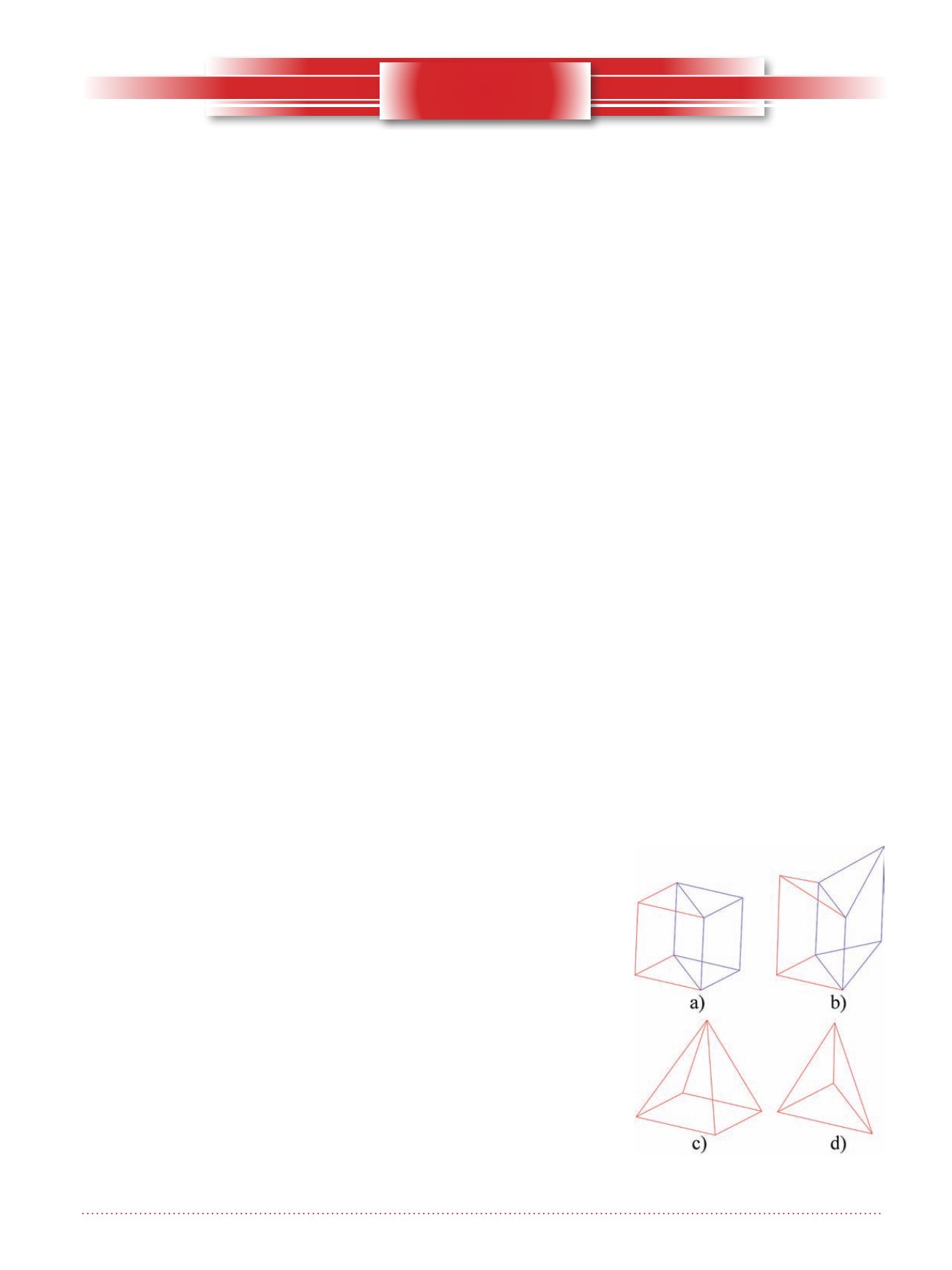
An extruded triangle was selected to
form the basic element for the new 3D
meshing tool. Two extruded triangles
can be arranged in a cubical shape,
as shown in Figure 1a. Note that the
basic element corners can be verti-
cally positioned at different elevations,
as shown in Figure 1b. In addition,
pyramid
(
Figure 1c) and tetrahedral
(Figure 1d) elements can be used for
transition schemes; they are minimally
Figure 1. Base elements for meshing
tool.


