Geotechnical News • September 2012
31
GROUNDWATER
with the non-linearity of the equations
and hydraulic parameters.
Start with the mesh refinement
When using any code for unsaturated
seepage, the first step is to reduce
the element size to avoid potential
numerical oscillations, and ease the
convergence process. This is verified
using steady-state (time independent)
conditions. The second step is to
reduce the time step to ensure proper
convergence towards the correct
solution, and not towards an incorrect
solution.
This paper examines only the first
step, reducing the mesh size for
steady-state conditions.
Any seepage problem usually has a
saturated domain and an unsaturated
domain. The meshing rules of previ-
ous companion papers (Chapuis 2010,
2012) can be used for the saturated
domain, which helps to avoid poor
numerical results (Chapuis and Chenaf
2010). For the unsaturated domain, a
simple meshing rule can be obtained
by observing the graphs of
θ(u)
and
K(u)
. In the example of this paper, a
single soil will be used with the func-
tions of Fig.1. Consider two points
A and B in the steepest zone of the
K(u)
graph (Fig. 1b): for a suction (
u
)
drop of 2 kPa, from -4 to -6 kPa, the
K
value drops from 10
-5
to 10
-7
m/s.
Consider now a no-flow condition in
a vertical column: the hydraulic head
(or total head) is constant. A suction
change of 2 kPa occurs for an eleva-
tion change of about 20 cm. The data
of Fig. 1b thus indicate that the
K
value may change by two orders of
magnitude over a vertical distance of
20 cm. In numerical calculations, the
code will have to select some mean
K
value within each finite element. If
the finite elements are 20 cm high, the
mean
K
value has to be selected by
the code within a range of two orders
of magnitude: there will be tenden-
cies for overshooting or undershoot-
ing, and thus numerical convergence
issues. If the elements are 10 cm high,
the mean
K
value for each element
has to be selected over a range of
one order of magnitude: there will be
fewer numerical issues.
As a rule of thumb for meshing unsat-
urated zones, we suggest to restrict
the element height to the value giving
a maximum change of one order of
magnitude for
K
under a no-flow con-
dition. This corresponds to elements
10-cm high for our example (Fig. 1).
This rule of thumb produces adequate
initial meshes for
engineering problems, for example
assessing the unsaturated drainage
conditions in highway foundations.
However, it may yield very large
meshes for regional groundwater
problems. For example, if the water
table in an aquifer has a yearly fluctua-
tion of 2 m around a mean position
at a depth of 3 m, there will be a 5
m (3+2) deep vadose zone in which
the water content
θ
and the hydraulic
conductivity
K
will vary with time. In
aquifer soils
K
typically varies by 4 or
6 orders of magnitude in the vadose
zone. It would be incorrect to numeri-
cally treat a 5 m high vadose zone
with five rows of 1 m high elements.
The mesh must be refined with ele-
ments about 10 cm high (or smaller)
for the vertical distance along which
K
has large variations, which can be
known by examining the K(
u
) graph.
This means using 30 to 60 more lay-
ers of elements for the vadose zone,
which may double or triple the total
number of elements in the mesh, as
compared to using 1 m high elements
in the vadose zone. As a result, the
computing time to reach a certain con-
vergence criterion may be multiplied
by a factor of about 5 to 20. If the
computing time was 36 hours with the
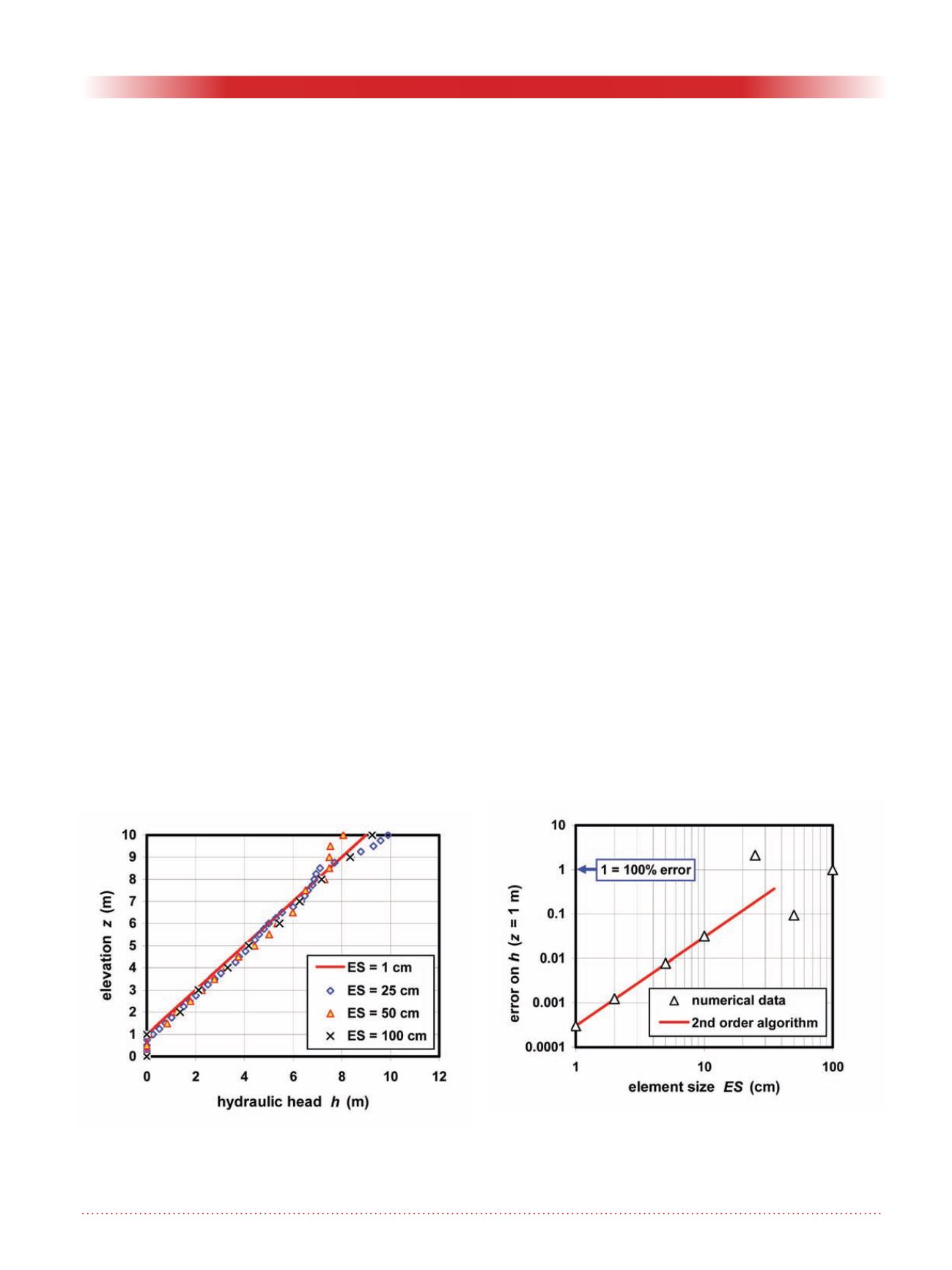
Figure 2. Numerical results for uniform meshes: Note the
numerical oscillations of hydraulic head h versus eleva-
tion z.
Figure 3. Example of results for uniform meshes: The
numerical error on h (z = 1m) is random (oscillating) for
large elements, and diminishes when the element size is
decreased.


