36
Geotechnical News • September 2012
used in the entire mesh, only between
5 – 10%.
By joining and stacking these ele-
ments a complex topographic form
can be constructed.
The use of the extruded triangle and
arrangement in a semi-structured man-
ner ensures creates a well balanced
mesh.
The steps for developing 3D meshes
are:
1. Create a 2D triangular mesh using
as a guide the contour plan of the
study area;
2. Assign an elevation to each triangle
corner. The mesh file created in
Step 1 can be cross referenced
with the CAD topography to pro-
vide the elevation at each triangle
corner; and
3. Use one of the meshing tools to
form the 3D model to the depth
required for the analytical study.
Meshing example
To illustrate the power of the meshing
tools a 3D mesh will be developed for
a cross-valley mine-waste dam using
Flac3D. Initially a starter dam will
be constructed in the valley and the
dam is then raised in stages to accom-
modate the production of the mine
tailings.
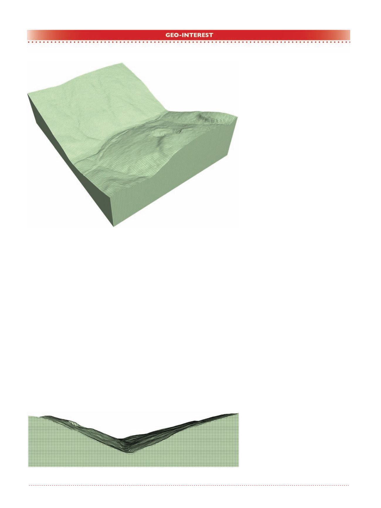
Figure 2 shows the valley model with
the main features, such as creeks,
scarped areas and a road on the right
side of the valley. The meshing tools
produced the 590 000 elements shown
in Figure 2, in only 5 minutes of com-
puter processing time.
Figure 3, a side view of the valley,
demonstrates two important character-
istics of the meshing tool.
• the number of elements at the
higher elevations of the topog-
raphy is greater that the number
of elements at the bottom of the
valley. The algorithm reduces the
number of elements as it moves to
lower elevations; and
• the elements are kept about the
same size across the model, thus
producing balanced meshes.
This last point becomes is very
important when performing dynamic
analyses.
Once the topography surface has been
developed the dam is inserted onto the
topographic form.
Figure 4 shows the Starter Dam - it
has a height of 38 m, a crest width of
10 m with upstream and downstream
slope of 2:1.
Figure 5 shows the final configuration
for the dam, it has a total height of 90
m, a crest width of 15 m, and the same
slope configuration as in the coffer-
dam.
Figure 6 shows a cut section of the
model through the dam downstream
toe. Each layer in the starter dam (as
well as in the mine-waste dam) is hori-
zontal, thus by individually activating
them allows for construction simula-
tion. In addition, this figure shows two
different stages of the dam construc-
tion. The user can use as many stages
as necessary to simulate raising of the
dam.
Integrating these structures into the
model is automatic and seamless. The
meshing tool takes care of this process
by updating the connectivity, selecting
the appropriate element at transitions,
and merging the repeated nodes and
faces.
Finally, it is very easy to insert the
mine-waste dam into a model. The
user only has to input 5 geometric
parameters; the crest location, eleva-
Figure 3. Valley side view.
Figure 2. Valley mesh.


