20
Geotechnical News •September 2015
GEOTECHNICAL INSTRUMENTATION NEWS
were objections to removal of the
system. These generally came from
occupants of buildings adjacent to the
cut and cover stations. After 13 years
of continuous monitoring they were
accustomed to the security provided
by the system. This was especially so
for the inhabitants adjacent to one sta-
tion where a number of construction
incidents had occurred that resulted
in very severe localised settlements.
In the initial stages of close-out
monitoring removal of the systems
was discussed with these groups. By
addressing their concerns the stake-
holders were then convinced the moni-
toring system was no longer required.
General - removal of a
monitoring system
Removal was the final element of the
contract awarded to Soldata-Grontmij
JV (SG) (by Dienst Metro (DM), who
procured the Metro line for the Munic-
ipality of Amsterdam (MoA) who had
installed, maintained and operated the
monitoring system. The main compo-
nents to be removed were:
• 74 RTS including computers, sup-
port brackets, wiring and power
boxes.
• Over 6000 prisms.
• Communication infrastructure,
including Wi-Fi, 3G modems,
brackets, wiring and aerials.
• Combined in-place inclinometer/
extensometers, piezometers and
associated infrastructure, such as
access chambers; ducts, cabling,
data loggers & instruments.
• Power supplies.
A number of these elements were to be
removed from the exterior of historic
buildings such as Amsterdam Central
Station, Beurs van Berlage (the old
stock exchange) and De Munt Toren.
To ensure that there were no building
damage issues or planning problems,
the removal had to be undertaken in
an agreed fashion. Guidance in the
contract was that after removal the
contractor was responsible for making
good the underlying materials.
Given this requirement DM and SG
agreed on a removal strategy dictated
by:
• Duration: A shorter time span for
removal was more cost-effective
for SG. This required DM to
streamline permissions from
various departments within MoA,
building occupants and other
stakeholders and communicate
those plans in a timely fashion to
occupants and building owners.
• Quality: Fast tracking was permit-
ted providing only that quality was
not compromised. SG trialled a
number of removal/making good
methods to various materials
before work commenced. The suc-
cessful methods were implemented
and a rigorously documented
system put in place. Each element
to be removed was photographed
both before and after removal.
Removal of monitoring
equipment
Robotic total stations and monitoring
prisms
The main component was the support
bracket removal. During removal a
number of issues were encountered.
Accessibility: Not all prisms and
instruments were located on readily
accessible places. This meant that
sometimes the trade-off was made to
not maintain or remove certain prisms.
Making good: After removal holes
(diameter 8 mm) remained. The
contractor was obliged to making
this good. DM specified a number of
requirements for this filling:-
• Aesthetically pleasing, e.g. flush
with surface and matching colours
of surrounding material.
• Ability to fix to a number of sub-
strata.
• Not sensitive to differences in
temperature (i.e. low alpha coef-
ficient).
• Life expectancy similar to the sur-
rounding materials.
Generally the material to which RTS
brackets and prisms were attached
consisted of brick, (from relatively
new to very old), mortar joints and
natural stone. Two main filler types
were considered:
• 2-part epoxy based mortars
• Cement based mortars
After careful consideration and trials
of both materials, epoxy mortar was
the preferred option. Both could fulfil
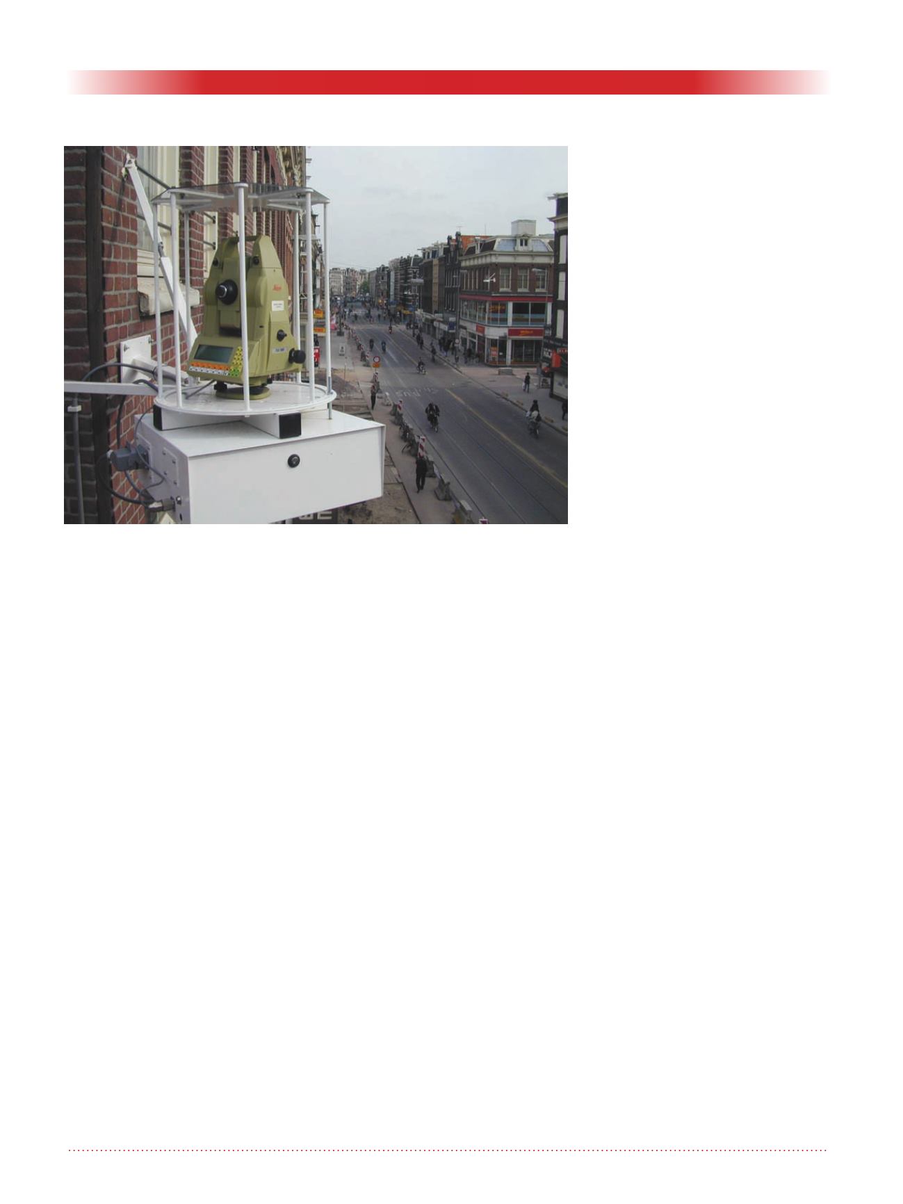
Figure 1. Typical RTS installation – (Photograph courtesy of SolData; all
rights reserved).


