Geotechnical News • June 2016
47
GROUNDWATER
to 55 cm for liner No.1, and from 23
to 59 cm for liner No. 2. The samples
had a few subvertical cracks crossing
the full thickness. In addition, 30% of
clay samples contained thin, less than
1-mm thick, layers of sand within the
clay liner, probably resulting from
poor handling of materials during con-
struction. Therefore, the first suspected
reason for poor performance, some
clay damage or poor quality work
in the upper parts of the slopes, was
verified.
The second suspected reason, a poor
seal along the pipes, was also inves-
tigated. During a site visit, when the
water levels had been lowered, the
author could see open spaces just
below the pipes with widths between
5 and 8 cm. The spaces were sounded
using a rod: they were opened along
the full liner thickness. Smaller (1-2
cm) open spaces were also found
above and around the pipes, after the
crushed stone had been removed to
expose the contact between clay and
pipe. A representative pipe is shown
in Fig. 4. Thus, the second suspected
reason was also verified.
Reason for the poor seal along
the pipes
Initially, the clay had been tightly
compacted against the pipes, which
had been installed during dike con-
struction and before liner construction.
Subsequently, a gravel protection was
laid everywhere over the liner, with
a special shape and increased thick-
ness around the ends of the pipes, as a
protection against erosion. The open
spaces that were found along the pipes
may have been caused first by thermal
dilation and contraction, and then
enlarged by water erosion.
The pipes were laid in June. The field
inspector reported that the contact
between clay and pipe was good.
During its installation, a pipe was at a
temperature close to that of the newly
placed clay (≈ 10°C). However, in
the next few weeks, its temperature
increased significantly (from about 10
up to 35
°C),
because the empty pipe
was in contact with the hot air inside
it. All pipes were made of plastic.
Their thermal dilation coefficient is
about 12 times higher than that of
cement concrete or steel (Chapuis
1990a). Therefore, the plastic pipes
dilated, their wall pushed away the
clay, thus tightening the seal at the
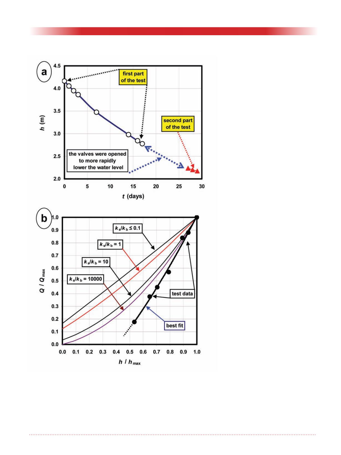
Figure 3. Full-scale leakage test, lagoon 2: (a) water level versus time; (b)
non-dimensional graph of relative flow rate Q/Qmax versus relative water
thickness h/hmax for the same lagoon geometry.


