Geotechnical News • June 2017
29
THE GROUT LINE
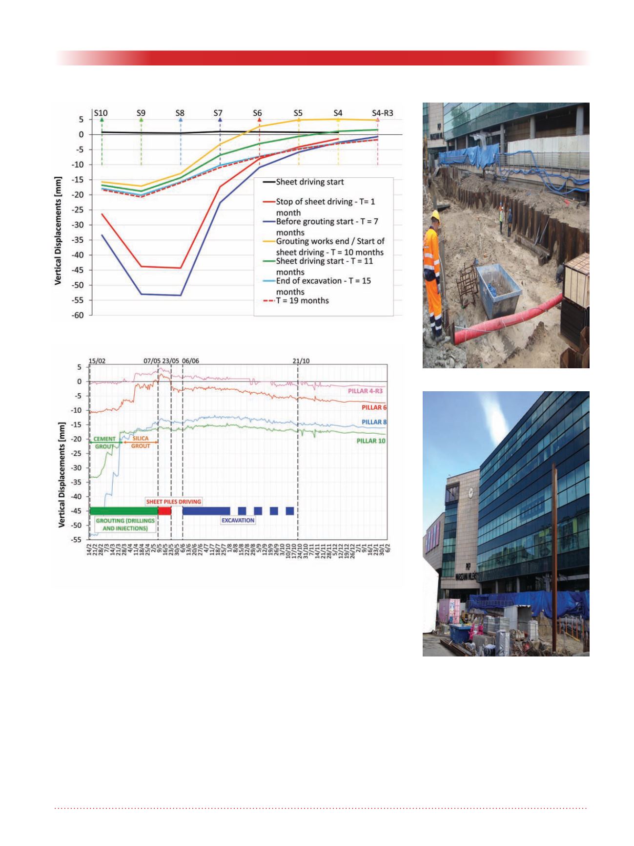
Few holes required an additional sec-
ond stage of cement grouting. When
the differential settlements between
the pillars were strongly reduced, the
silica grout was injected, working
gradually along the area to be treated.
The effect of this injection stage is
shown by the yellow line in (Fig.10);
an average uplift of about 5 mm was
induced.
At the end of the treatment, the sheet
wall execution was also completed in
the area in front of pillars nr. 6 to nr. 3.
The sheet elements were now driven
into the ground without vibration. The
green curve in the following figure
11 evidences the effect of this work
on the structure. Settlements of about
5 mm were measured in the zone
besides the activities, while pillars
nr. 8 and 9, showed a very reduced
settlement (less than 1.5 mm) after the
compaction grouting works.
Finally, the excavation between the
driven sheet walls and the following
reinforced concrete lining cast was
carried out in the following 4 months.
Low residual settlements were
measured, varying from 1.5 mm to
3 mm, in the range expected by the
structural designers. The effect of the
treatment, together with the different
execution methods used, definitely
allowed for reduction of the sensitivity
Figure 11. Pillars nr. 10, 6, 8 and 4R3 displacements during all the working
phases.
Figure 10. Pillars’ displacements during the time.
Figure 12. Warsaw worksite.
Figure 13. Warsaw worksite (2).


