24


            Geotechnical News •  September 2019


            GEO-INTEREST


          designed air-vane motor. The drainage
        
        
          element which was attached above
        
        
          the vibrator consisted of a structurally
        
        
          supported Johnson Well Screen. The
        
        
          exhaust from the air motor was used to
        
        
          blow seepage water out of the sys-
        
        
          tem.  Both elements measured about
        
        
          1.5m (5ft) in length and were 190mm
        
        
          (7½”) outside diameter. The deploy-
        
        
          ment method involved pushing these
        
        
          elements and similarly sized extension
        
        
          pipes into the ground using a drill rig.
        
        
          Then, when the assembly reached the
        
        
          required depth to be densified, the air
        
        
          motor was activated and the string
        
        
          gradually withdrawn to the surface
        
        
          again.


            COGLA


          preference was for the


            PM


          idea, whereas


            GCR


          wanted to use
        
        
          blasting because it could be done
        
        
          more quickly.  It was during this
        
        
          period of hesitation that


            PEL


          built a
        
        
          prototype of the


            PM


          described above
        
        
          and field tested it on the ship-impact
        
        
          sand berm protecting the north pier of
        
        
          Annacis bridge
        
        
          in Vancouver.
        
        
          The results were
        
        
          good.
        
        
          In the event, we
        
        
          mobilized what
        
        
          was necessary
        
        
          to perform the
        
        
          work using either
        
        
          explosives or
        
        
          vibro-drainage.
        
        
          By then


            COGLA


          had been talked
        
        
          into the blast-
        
        
          ing option and
        
        
          therefore that is
        
        
          how the work
        
        
          began, all going
        
        
          smoothly until
        
        
          instrumenta-
        
        
          tion showed
        
        
          that vibrations
        
        
          in some steel
        
        
          members were
        
        
          exceeding their
        
        
          structural limit
        
        
          (13”/s) as soon
        
        
          as charges were
        
        
          detonated within 3.7m (12ft) of the
        
        
          core walls.  That prohibition meant
        
        
          the sandfill most vulnerable to the
        
        
          effects of ice pounding would be left
        
        
          untreated.  It was at this stage


            GCR


          asked us to deploy the


            PM


          to fin-
        
        
          ish the densification job.  This extra
        
        
          work went without a hitch, with large
        
        
          volumes of seepage water being dis-
        
        
          charged from the machine.  At the few
        
        
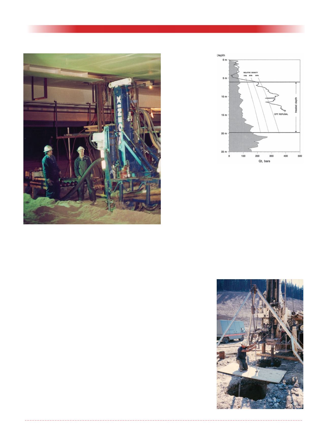
          locations where CPT probes made a
        
        
          direct hit on the top, buried 7m (23ft)
        
        
          down, of one of the sand columns
        
        
          created by the


            PM


          the results showed
        
        
          relative densities generally exceeding
        
        
          90% (Ref 3). One of these traces is
        
        
          shown in Fig 3, where the background
        
        
          shaded area shows the condition
        
        
          achieved by blasting.


            Black Dome Mine


          During our field work on the upstream
        
        
          face of the tailings dam at the Black
        
        
          Dome goldmine in the Chilcotin area
        
        
          of BC we observed something new.
        
        
          Cylindrical holes appeared around
        
        
          each location at which the


            PM


          was
        
        
          activated, see Fig 4.
        
        
          The tailings grind was 95% passing the
        
        
          #200 sieve and accordingly its perme-
        
        
          ability was quite low; in consequence,
        
        
          there was very little seepage water
        
        
          discharge.  It is a geotechnical fact that
        
        
          the quantity of flow is dependent upon
        
        
          permeability, whereas the magnitude
        
        
          of seepage forces is not. Therefore, the
        
        
          amount of water discharge at ground
        
        
          level is no indicator of the effective-
        
        
          ness of the


            PM


          at depth.


            Figure 3: CPT trace of PM results at


            Molikpaq.


            Figure 4: Craters at Black Dome.


            Figure 2: Work space under Molikpaq deck.