26
Geotechnical News • September 2019
GEO-INTEREST
Improvements in the
PM
’s
design
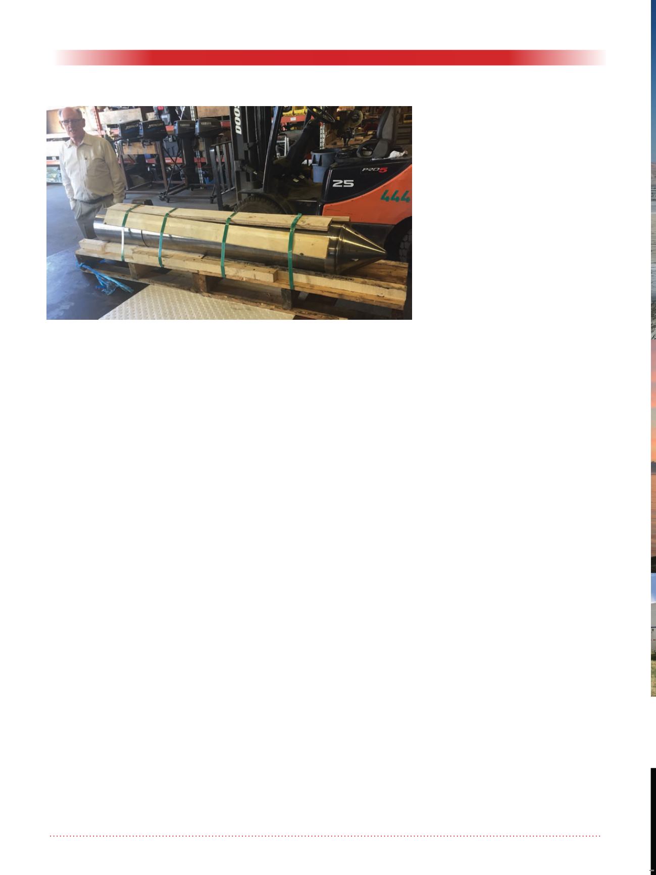
Fig 7 shows the current
PM
as it is
comes from the machine shop. It
differs from the machine used at
Molikpaq and at the two mine sites
discussed above. In the earlier mod-
els the filter/drain stood above the
air-motor and eccentric, making the
overall machine length 2.9m (9.4ft).
In this case the seepage intake sec-
tion is wrapped around the vibrator
thereby reducing the overall length
to 5ft (1.5m); the OD in both cases is
the same 190mm (7½”). The power
source will now be top-drive using the
contractor’s choice of engine.
Apart from that there have been two
recently patented additions to the
PEL
toolkit :
1. In weaker ground environments,
such as deltaic deposits and mine
tailings of various gradations,
the filter of the well screen could
become impervious if the open
spaces between its helically wound
wire became plugged by cohesive
layers existing within the material
being treated. A newly devised
module (US patent 10240314),
capable of rectifying this situation
will henceforth become a stan-
dard part of the
PM
. Of practical
importance is that this capability to
remove such smearing can be acti-
vated remotely while the machine
is still at depth.
2. What we call our Trident deploy-
ment array (US patent 8419316)
consists of three separate
PM
strings structurally harnessed
together so that their long axes are
vertical and are spaced apart later-
ally in an equilateral configuration.
The mere fact that there are three
excitable tools in the ground at the
same time, and in close proxim-
ity, opens a whole new prospect
in ground improvement technol-
ogy. This is because each of the
three neighbouring machines can
be made to perform their functions
independently, leading to many
combinations of their vibratory
and hydrodynamic forces. Two
applications of this configuration
come to mind:
a. The soil within the compass of the
three separate prongs could be
made into a very dense column
which would provide seismic-re-
sistant deep foundations capable of
carrying heavy structural loads.
b. Water could be pumped into, or
sucked out of, the ground by
each poker either in tune with its
partners, or in a cooperative man-
ner such as to create a flow in any
lateral direction between them.
This procedure could be enacted in
order to clean up polluted ground-
water in the soil between the
pokers.
Summing up
My hope is that what is presented
above, from field observations and
data recorded at three distinctly differ-
ent sites, is sufficient to convince the
reader that the Phoenix Machine hard-
ware and our procedures, are worthy
of consideration when geotechnical
engineers and ground improvement
contractors are faced with the prob-
lems arising out of loose or weak
foundation conditions. And, to quote
Ralph B. Peck: “Whatever the expla-
nation, I think your idea of simultane-
ous vibration and drainage has a lot of
promise in practice” (Ref 4).
Please note: More detail and data than
can be printed here can be found at
References
Donald W. Taylor (1948) Funda-
mentals of Soil Mechanics, John
Wiley, London.
W.E. Hodge (1988) “Construction
Method for Improving Underwater
Sand Fills” ASCE
Geotechni-
cal Division,
Specialty Conference
on Hydraulic Fill Structures,
Fort
Collins.
G. Baldi et al, (1982) “Design Parame-
ters for Sands from CPT”,
Pro-
ceedings of the Second
European Symposium on Penetra-
tion Testing,
ESOPT II, Amster-
dam, Vol 2.
R.B. Peck, (November 1998) Personal
correspondence.
William E. Hodge
Figure 7: The current PM as delivered by machine shop.


