32
Geotechnical News March 2011
GEOTECHNICAL INSTRUMENTATION NEWS
intrados and one at the extrados in cir-
cumferential direction. The four sec-
tions are equally spaced around the
ring circumference. In order to esti-
mate axial force and bending moment
in the permanent lining of the Buttoli
tunnel, a cross section was provided
with five pairs of strain gauges, equally
distributed along the lining: a pair for
each side, one at the crown and other
two intermediate points. The invert was
not instrumented. In both the example
cases, the strain gauges were welded to
steel bars.
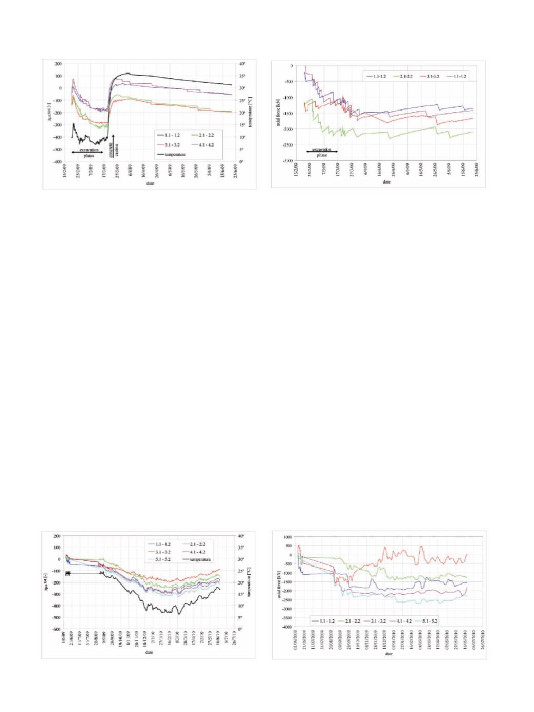
In the following figures, the cor-
rected measured total strains, averaged
in each instrumented section between
extrados and intrados, and the corre-
sponding axial forces, computed by
the proposed procedure, are shown for
both the ring beam (
Figure 2
a, 2b) and
the tunnelling example (
Figure 3
a, 3b).
Each curve refers to a pair of strain
gauges; as for the tunnelling example,
1.1-1.2 and 5.1-5.2 correspond to the
pairs of strain gauges placed on the
left and right sides of the tunnel lining,
3.1-3.2 to the one placed at the crown
and the remaining ones to the two in-
termediate points. In the total strain
versus time figures, temperature inside
the concrete is also plotted. In
Figure
2
a, the effect of the temperature rise
due to concrete casting on the strain
values is clear, whereas, in a similar
way, the effect of seasonal temperature
variation on the concrete strain can be
seen in
Figure 3
a. The maximum val-
ues of axial force derived by the mea-
surements turned out to be in both case
studies within the design values: in the
first case, the measured value is almost
70 % of the design one, whereas in the
second case the maximum measured
value is equal to 65% of the design val-
ue. Such differences can be explained
by precautionary assumptions adopted
in the design phase.
The importance of applying the cor-
rect conversion procedure is shown in
Tables 1 and 2. For each of the two
considered examples, the final axial
forces computed by the proposed pro-
cedure (N1) are compared to the ones
derived by disregarding respectively:
• N2: shrinkage and aging (i.e. chang-
ing Young’s modulus with time);
• N3: creep and aging;
• N4: creep and shrinkage;
• N5: considering concrete as simply
an elastic material (i.e. disregard-
ing all time-dependent effects).
As is clear by comparison between
N1 and N5, if the conversion procedure
is too simplified, the stresses can be
overestimated by a factor of nearly six.
Conclusions
In order to obtain reliable estimates
of stress by installing strain gauges
embedded in concrete structures or
welded to reinforcement bars, a proper
conversion procedure must be adopted.
The proposed procedure takes into
account the complex behaviour of
concrete by considering the effect of
shrinkage, creep strain and hardening.
Such a procedure can be easily
implemented by an Excel spreadsheet
and a Visual Basic routine. As shown
by the examples, the proposed
procedure leads to results that can be
compared to the design estimations,
whereas adopting too simplified a
Figure 2a. Ring beam - Measured in strain vs time.
Figure 2b. Ring beam – Computed axial force vs time.
Figure 3a. Tunnel lining – Measured strain vs time.
Figure 3b. Tunnel lining – Computed axial force vs time.


