26
Geotechnical News June 2011
GEOTECHNICAL INSTRUMENTATION NEWS
combination by the focusing technique
of radar images that are acquired during
the movement of the antennas allows
2D SAR images to be obtained. These
images are characterized by range
(instrument-scenario joining direction)
and cross-range (direction normal to
the range direction in the horizontal
plane) resolution (Figure 1). The final
SAR image consists of several pixels
whose size strongly depends on the
equipment features and on the radar-
scenario distance.
By comparing the phase difference,
i.e interferometric technique, of each
pixel of two or more SAR images col-
lected at different times, the displace-
ment along the instrument line of sight
can be estimated by using the follow-
ing equation:
where
d
is the displacement, λ is the
wavelength of the radar signal and ∆φ
is the phase difference between the
two acquisitions. However, additional
processing aiming at remove the
atmospheric noise is required. The final
output of TInSAR monitoring is 2D
color images where the magnitude of
displacements along the instrumental
line of sight, in the computed elapse of
time, can be quickly identified (Figure
2). In addition, displacement time
histories of each pixel of the image can
be achieved.
The pixel resolution of a SAR image
ranges from few decimeters to several
meters (depending on the equipment
and on the monitoring distance) and
the displacement accuracy ranges from
few tenths of millimeters to a few mil-
limeters, depending on the operational
distance and the atmospheric condi-
tions. For example, at a distance of 1
km, commercial equipment has a range
resolution of about 0.5 m and a cross-
range resolution of 4 m; as regards the
accuracy values ranging from 0.5 to 3
mm are reasonable at a distance of 1
km. This equipment has a maximum
range capability of few kilometers
and a maximum temporal frequency
of images collection of few minutes.
However, future TInSAR equipment is
expected to be faster in data collection
and smaller in size.
Advantages and Limitations
As already stated, TInSAR is one of the
two “real” remote monitoring sensing
techniques, since it does not require the
installation of sensors or targets in the
monitored area. This is probably one of
the main advantages of TInSAR as the
access to the monitored areas is often
dangerous (e.g. active landslides),
difficult (e.g. cliffs) or prohibited by
local authorities, such as heritage
situations. Sometimes, we are faced
with movements so rapid, e.g. rapid
landslides, that sensors are quickly
destroyed or made unusable. In these
cases remote TInSAR monitoring can
be an efficient solution. An additional
advantage is related to the control of
an area (i.e. pixel) instead of single
points identified by sensors, reflectors
etc. This feature can reduce the
misinterpretation, which is a frequent
problem in the case of points-based
monitoring. On the other hand, the
analysis of an area instead of a point
can also be a limitation if this area
behaves in a heterogeneous way, or if
the monitoring of a specific point is
required. In these cases passive corner
reflectors for TInSAR can be installed,
thus allowing the increase of the signal
to noise ratio of the pixel and also the
precise identification of the monitored
point.
A further advantage of TInSAR is
the full operability under all lighting
(day and night) and weather conditions
(rainfalls, clouds, fog etc).
A significant advantage is the ability
for “spatial” monitoring. This means
that TInSAR can be used to simulta-
neously monitor the displacement of
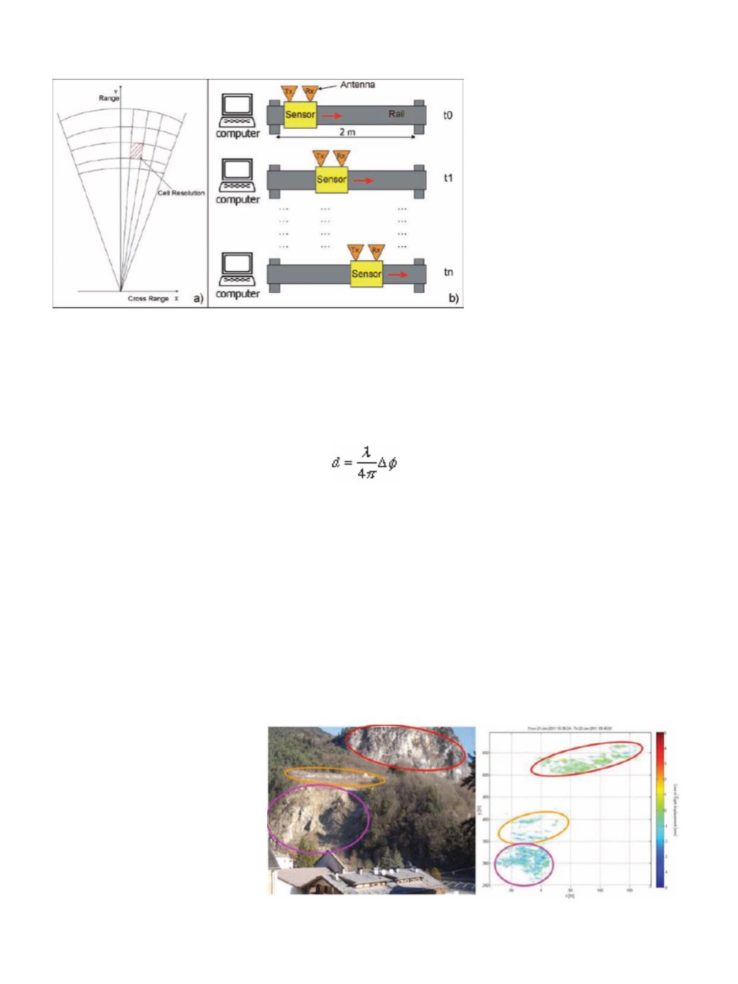
Figure 1. a) Resolution cell of RADAR maps; b) Synthetic aperture obtained by an
antenna moving along a rail.
Figure 2. Picture of a slope (on the left) and TInSAR displacement image (on the
right). Color ellipses enclose corresponding parts of the investigated slope.


