Geotechnical News December 2011
27
GEOTECHNICAL INSTRUMENTATION NEWS
ous materials typically used for back-
fill when installing a VWP in a boring.
Water pressure was applied from the
bottom of the chamber directly on to
the surrounding material, a distance
of 4 to 7 inches from the diaphragm of
the VWP. Therefore, the water pressure
had to propagate through 4 to 7 inches
of the surrounding material before it
reached the piezometer diaphragm. In
order to model field conditions, I at-
tempted to saturate all surrounding
materials by introducing de-aired wa-
ter into the bottom of the test chamber
and allowing air to escape out of the
top, until water was flowing out of the
top of the chamber. Then I capped the
top of the chamber and began apply-
ing pressure and recording data. This
method resulted in incomplete satura-
tion of the grout and clay. I suspect that
the incomplete saturation may have re-
sulted in slower response times.
To setup the tests, the VWP was
suspended in the triaxial test cham-
ber, and the surrounding material was
placed around it. For sand, water and
clay, I had the triaxial chamber con-
nected with the top and bottom plate,
and poured the surrounding material
through the hole in the top. For grout, I
created a false bottom with mastic tape
and a plate approximately 1 inch above
the bottom of the cylinder. The VWP
was suspended in the cylinder over this
false bottom, and grout was poured in
and allowed to cure. Two Geokon mod-
el 4500 VWP sensors were used, with
pressure maximums of 250kPa, both
of which were periodically tested for
accuracy by submerging them in the
triaxial test chamber filled with water,
applying pressure into the chamber,
and observing the pressure recorded by
the VWPs. I tested to see if varying the
installation methods and surrounding
material affected the response times,
or ultimate accuracy of the instrument.
Each installation method was tested
twice, once with each VWP.
Methods of installation for the VWP
tests are presented in Table 1:
The sand I used in the testing was
Colorado silica sand. The grout mix
was 1 gallon water to 3 lb cement to
approximately 1 lb bentonite grout. To
mix the grout, water and cement were
added and mixed first in a 5 gallon
bucket, and then bentonite was added
and mixed in. I used the Mikkelsen and
Contreras et al method of grout mixing,
adding bentonite until a consistency
was reached in which the grout formed
craters when dripped. New batches
were mixed for each separate test, and
the grout was allowed to cure for 48
hours. The bentonite chips were 3/8
inch chips, hydrated for approximately
a week.
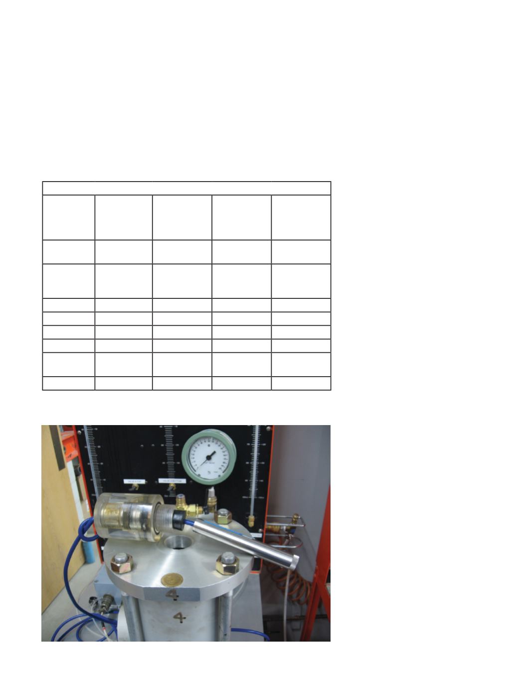
Figure 1 shows the typical setup
before the VWP is installed. The back-
ground is the triaxial compression test
frame that was used to apply pressure
to the chamber. I connected the VWP to
a datalogger, which recorded the VWP
data every 5 seconds. I compared data
from the VWP to the pressure applied
by the triaxial compression test frame.
Table 1. Tests of VWP Installation Methods
Test Number Surrounding
Material
Diaphragm
Tip Direction
Pre-Saturated
(test a) or Not
(test b)
Using a
Protective
Canvas Bag or
Not
1 (a and b)
Water
Up
Both tests
performed
No
2
Water
Down
No,
Intentionally
capturing air
No
3
Sand
Up
No
No
4
Sand
Up
No
Yes
5
Grout
Up
Yes
Yes
6
Grout
Up
Yes
No
7 (a and b)
Grout
Down
Both tests
performed
No
8
Clay
Up
No
No
Figure 1. Test setup.


