Geotechnical News December 2011
31
GEOTECHNICAL INSTRUMENTATION NEWS
to adapt to the site by running the ca-
ble through several short, horizontally
bored segments beneath a large drain-
age ditch, multiple road crossings, and
other obstacles at the surface. All cable
segments were later linked together, to
form a single sensing loop, by fiber-op-
tic fusion splicing. The splices between
segments, as well as some extra lengths
of non-buried cable, are stored in dedi-
cated, above-ground junction boxes,
that can be accessed for maintenance as
well as for re-routing segments of cable
in case a break were to be caused by the
formation of a sinkhole.
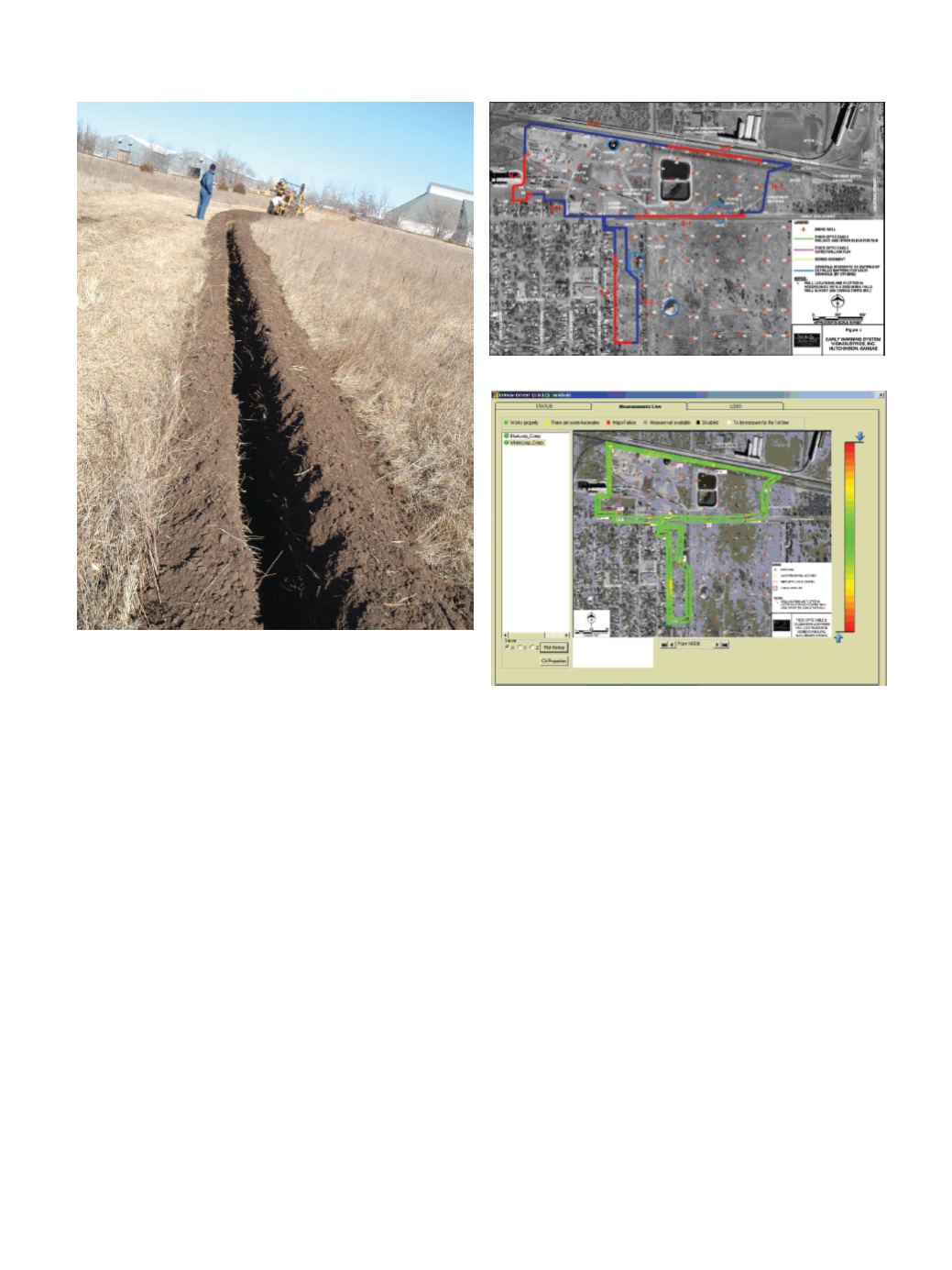
The final layout of the FO cable is
shown in Figure 3, the different co-
lours, with labels, are used to identify
the different cable sections spliced to-
gether.
After finishing the cable installation
and completing all the necessary qual-
ity/functionality tests on the sensing
cable itself such as sensor integrity test
by mean of visual fault locator, sensor
attenuation test by means of OTDR
measurements, Optical Time Domain
Ref lectometry,
quality of the FO
splices, the sys-
tem was ready for
commissioning
and final handover. The system com-
missioning mainly consisted of:
• Sensor parameterization
to optimize
system performances in terms of
strain resolution. In this phase us-
ing the FO system managing soft-
ware it is possible to set the length
of the sensor, the spatial resolution,
the measurement time and a series
of instrument parameters that influ-
ence the final system performance
in terms of strain resolution and ac-
curacy.
• Establishment and surveying of a
coordinate system to relate lengths
along the cable to specific marked
locations on the ground: a key as-
pect in a distributed monitoring
project is an established coordi-
nate system that will allow the pre-
cise position of an alarm triggered
by ground strain to be shown on
a computerized map. At a point
where ground strain is detected by
the cable, the software reports the
exact location along the cable, in
meters of distance from the end of
the cable, (essentially at location of
the computer). Luminous high-vis-
ibility signs were posted at the site
along the cable route, indicating
lengths from the end of the cable,
so that responders in the field can
quickly and accurately proceed to
whatever location the alarm indi-
cates. The coordinate system also
allows the definition of several spe-
cific alarms zones, according to the
client’s requirements, which will
be automatically handled by the
software.
• System functionality check: simula-
tion of ground settlement by arti-
ficial imposition of external force.
Tests were run in the field, along
temporarily un-buried segments of
Figure 2. Trench preparation.
Figure 3. Sensing cable layout.
Figure 4. Software for sinkhole project: Direct, real-time read-
out of ground strain along the cable.


