32
Geotechnical News •March 2015
GEOTECHNICAL INSTRUMENTATION NEWS
large landslide body or its deep remo-
bilisation? What is the range of the
expected displacement velocity? The
object to be monitored was not clearly
defined, and the monitoring system
was multi-purpose and complex.
The monitoring system consisted of:
• Probe inclinometers, for which
readings were collected either
every week or fifteen days.
• Observation wells and open stand-
pipe piezometers, for which read-
ings were collected every week or
fifteen days.
• Electrical resistance load cells
installed at the head of some of the
tiebacks.
• Topographical monitoring of the
three bulkheads by a total station
(Figure 2).
• In addition, the slope was moni-
tored by a terrestrial interferometer
(TInSAR) located in front of the
landslide slope on the opposite
side of the valley at a distance
of approximately 900m (Figure
3). Interferometric images were
acquired every five minutes.
• Hourly rainfall data and daily pho-
tographs were also recorded.
TInSAR monitoring was performed
by our research team, whereas other
companies were responsible for the
remaining instrumentation. Our task
was to collect all available data and
assist with managing the ongoing sta-
bilisation projects and tunnel excava-
tion.
During the six-year monitoring period,
many secondary instability events
were recorded, such as the occur-
rence of shallow and small landslides
in different sections of the slope, the
movement of excavation debris along
the slope (triggered by rainfall), the
failure of a metallic wall on short piles
(installed to protect the downslope
trail from excavation debris), and
the gravitational settling of gabions
located in the upper portion of the
slope.
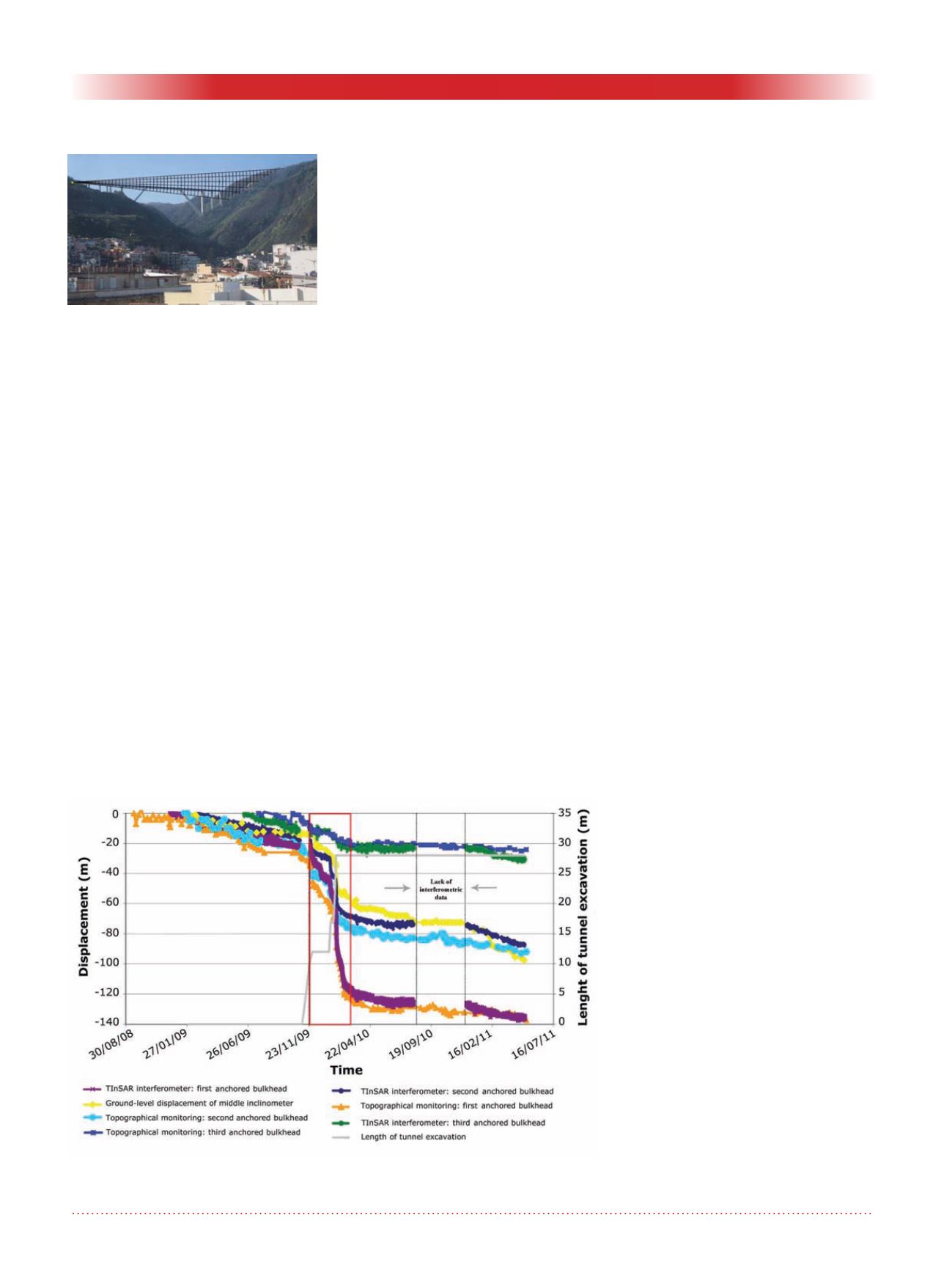
The main recorded event was the
reactivation of the larger landslide
from late 2009 to early 2010, when
the tunnel excavation restarted after
completing the remedial projects. All
instrumentation recorded the crisis
(red rectangle in Figure 4) triggered by
the excavation. However, only by the
continuous monitoring using terrestrial
interferometry the tunnel projects was
stopped when a displacement veloc-
ity of approximately 1 mm per hour
was determined for the first anchored
bulkhead.
This complex, redundant and expen-
sive integrated monitoring platform,
which was planned due to uncer-
tainties experienced by the
a priori
geological model, performed well,
which is indicated by the red bars in
Figure 1.
If a well-constrained and calibrated
numerical stress-strain model of the
slope had been done in order to simu-
late the effects of the excavation of the
tunnel on the stability of the quiescent
large landslide, attention would have
been concentrated on it. In that case
the monitoring would have consisted
mainly of continuously recording in-
place inclinometers.
Case history 2
This case concerns another category
of geological risks: subsidence. The
involved area (30 km
2
) is located
in central Italy, about 30km east
of downtown Rome. This area has
become intensively urbanised over
the decades. In certain small sections,
subsidence has caused extensive dam-
age to buildings and infrastuctures. A
large quarry basin containing traver-
tine (a
formed by
the
of
from solution in ground and surface
waters, and/or
It is used as building
material) is located within this area;
Figure 3. Photograph of the valley
in which the landslide occurred.
The slope involved in the instability
(right); the location of the terrestrial
interferometer (left). A sketch of the
area covered by the TInSAR moni-
toring is superimposed.
Figure 4. Displacement (left y-axis) and the tunnel excavation length (right
y-axis) vs. time monitored using different techniques.


