42
Geotechnical News • June 2018
GEO-INTEREST
mitted the request, Geo Meshing con-
nects with the Bing Map® server and
downloads the surface topographic
data. Depending on the location on the
planet, the downloaded information
can be very precise and up to date or
vice versa.
After the data has been downloaded,
Geo Meshing process the informa-
tion and it can create surfaces and
3D meshes out of it. The surface will
be shown in Geo Meshing graphic
window, as shown in Figure 2. Then
the 3D mesh can be imported into
FLAC3D
®
.
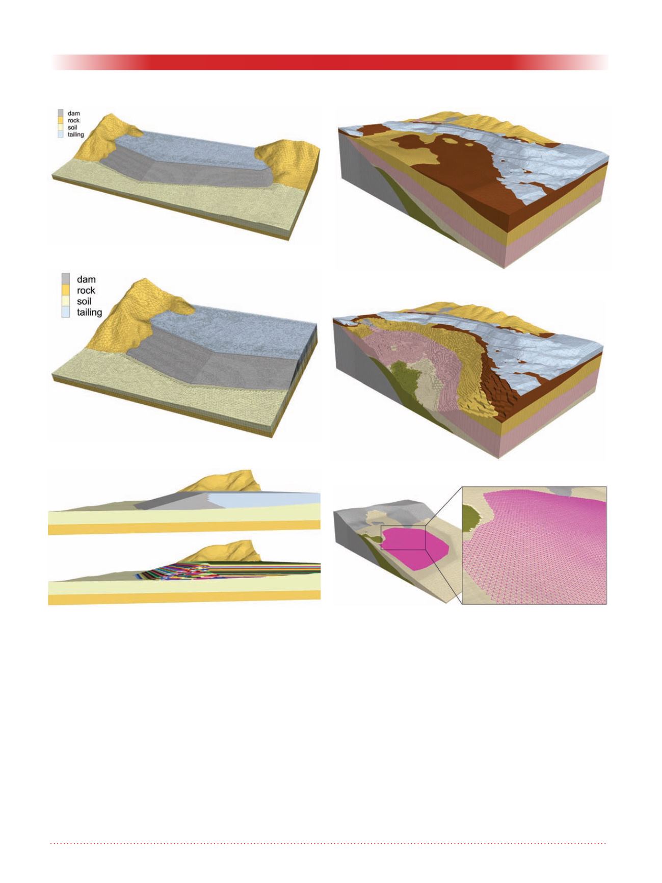
3D Sand Dam model
Figure 3 shows a full 3D model of a
sand dam. The mesh complexity of
this model lies in the dam geometry,
which is compromised by three align-
ments along its crest and the change in
construction technique. This last one,
refers to changing from downstream
construction to center-line construc-
tion (Figure 5). Another additional
complexity is the mesh refinement,
needed to obtain enough details at the
dam, but coarse enough away from the
dam, to avoid overloading the model
with excessive elements. The refine-
ment for this model was performed in
two ways, one in the horizontal direc-
tion (as shown in Figure 3) and one in
the elevation direction.
Figure 4 shows the localization of
a cut plane within the 3D sand dam
model, and Figure 5, in the upper
portion of it, shows the cut plane with
some background from the 3D model.
Figure 3. Full 3D Sand Dam model.
Figure 4. 3D Sand Dam model – cut plane.
Figure 6. Full 3D model – geological units.
Figure 5. 3D Sand Dam – cut plane with 3D back-
ground.
Figure 7. Full 3D model - geological units showing pit.
Figure 8. 3D interface.


