44
Geotechnical News • June 2018
GEO-INTEREST
CSattAR operates on ‘Sattar Image
Tracking’ (SIT) technique. SIT is
based on the same principles of ‘Digi-
tal Image Correlation’ techniques that
are widely used for laboratory experi-
ments and for short-term applications
such as bridge
vibration moni-
toring. SIT, on
the other hand,
is designed to be
robust for long-
term monitoring
practices where
light, tempera-
ture and weather
change.
The tracking
process involves
identifying the
new position of
pre-defined pix-
els within time-
lapsed images
and scaling
(reconstructing)
those movements
from image
coordinates into
global/metric
coordinates. In
long-term moni-
toring, the cam-
eras are likely to
experience tilt
and displacement
and this limits
the application of
using a camera
system to mainly
‘deformation’
monitoring rather
than ‘displace-
ment’ monitor-
ing. Also, movements are captured in a
two-dimensional space and there is an
imposed error that is caused by move-
ments along the third axis. CSattAR
is capable of quantifying these errors
and it often produces results that are
more accurate than using conventional
systems.
How does it compare to
Automated Total Stations?
The more projects I get involved with
the more I feel that our monitoring
work has been moulded by survey-
ing practices rather than follow-
ing engineering priorities. This has
made the industry adapt surveying
tools, focusing more on monitoring
‘displacements’ rather than ‘defor-
mations’ which are often the main
cause of damage. This evolvement
is understandable. In a construction
project, deformations such as strains
and angular distortions are not as
straightforward to interpret and they
are even harder to communicate or
manage. Automated Total Station
(ATS) systems bring that simplicity.
They will always be an important part
of a medium to large scale monitoring
project.
New technologies, such as CSattAR,
have the potential to reclaim measur-
ing some important deformations
without introducing complexities.
The following three deformations are
examples of this:
Convergence monitoring
The system has been installed in
several existing tunnels in order to
monitor and record the convergence
of tunnel sections/rings. This includes
monitoring the cast-iron rings of the
Central Line Tunnel and the Royal
Mail Tunnel (RMT) at Liverpool
Street Station area when influenced by
Crossrail work, RMT at Bond Street
Station area when influenced by the
Bond Street Station Upgrade work
(BSSU) and two of CERN’s concrete-
lining tunnels.
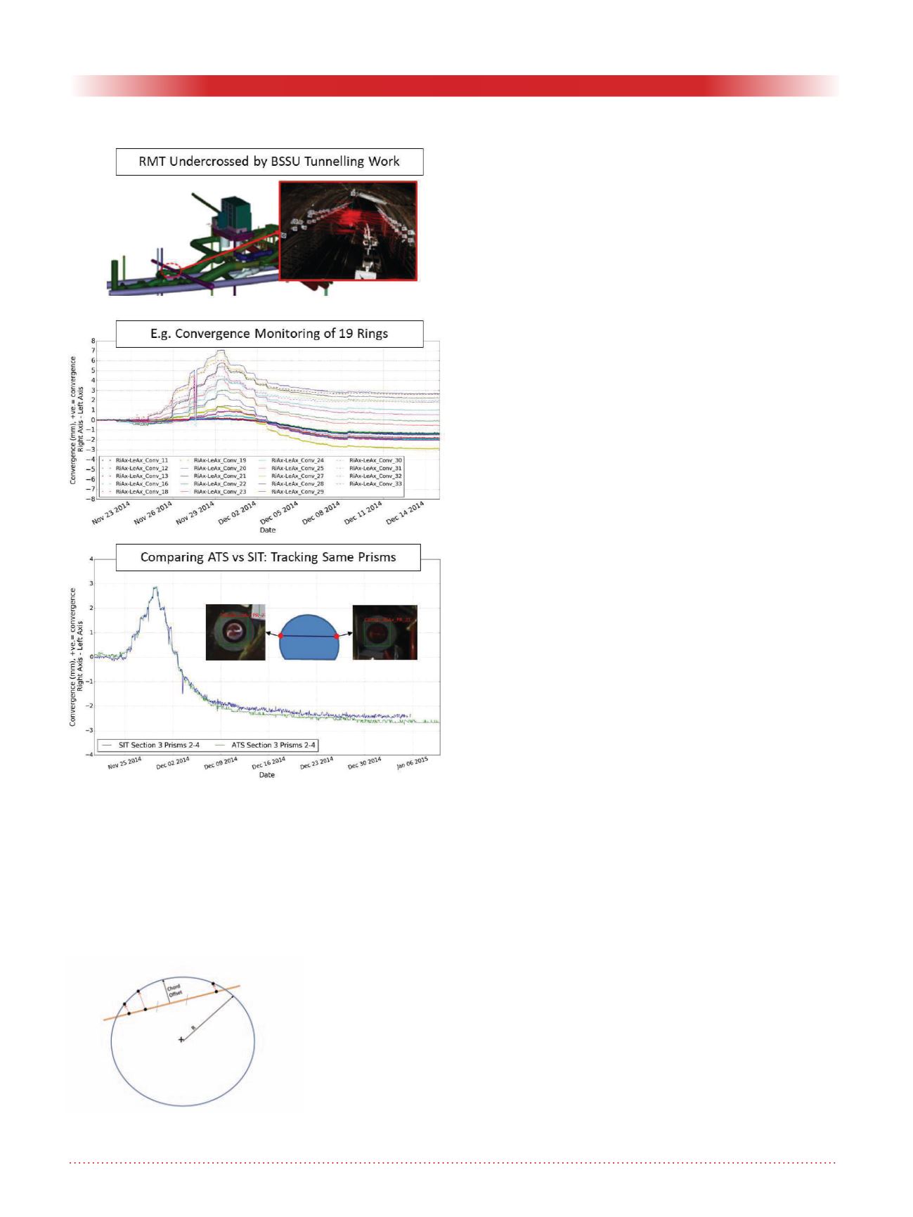
Convergence of tunnel sections/rings
is often carried out to ensure that tun-
nels do not undergo excessive ovali-
sations. Figure 01 shows the RMT
example at BSSU. In this case it was
possible to monitor the convergence
of almost every influenced ring (more
than 50 rings over 30m) by install-
ing three cameras. When tracking the
same prisms monitored by ATS, both
systems gave almost identical results
(Figure 01 – bottom).
CSattAR was able to measure a sig-
nificantly larger number of rings with
higher precision (as high as 0.01mm
when tracking CSattAR targets) and
at a fraction of the ATS costs. In
all of the cast-iron case studies that
Figure 2. Measuring R from three
displaced points.
Figure 1. Monitoring convergence of Every Ring at Royal
Mail Tunnel – Bond Street Station upgrade.


