Geotechnical News • June 2018
45
GEO-INTEREST
I have been involved in, there has
always been at least one ring that
performs weaker than others. This
can be flagged early when an ‘intense’
monitoring system such as CSattAR
is used.
Curvature monitoring
Monitoring locally imposed curva-
ture is a precision sensitive task. A
minimum number of three targets are
needed to measure curvature and it is
usually measured by fitting a circle
over the displaced new positions of
the monitored points and is quantified
by the radius of this circle, called the
radius of curvature (R). For smaller
chords, very small deformations can
cause critical curvatures. For example,
0.1mm movement of a point at the
centre of a 2m long chord (call it
chord offset) can cause 5km of R. At
Crossrail, 5km was set as a construc-
tion alarm trigger for London Under-
ground tunnels.
An ATS system (for example) is not
precise enough to be able to measure
R for such small chords, given that
the final precision of measuring R
depends on three separate target read-
ings. On the other hand, the CSattAR
system captures the position of all
points at one click, eliminating the
errors associated with monitoring at
individual instances. Coupled with its
high precision, CSattAR has been able
to monitor R for chords shorter than
2m.
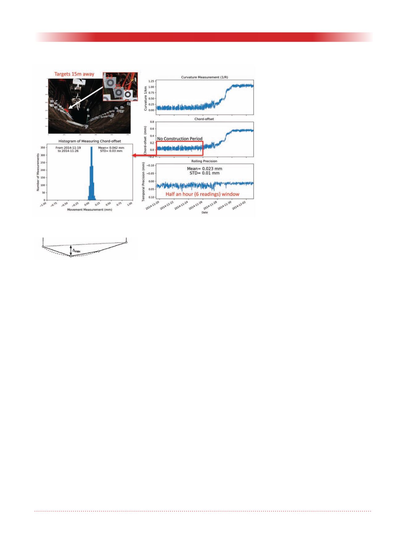
Figure 03 shows an example of
monitoring R of a 2m chord placed
15m away from the camera position
at RMT at BSSU. For this chord, the
total precision of measuring R, defined
as chord offset as shown in figure 02,
has been; 0.03mm when looking at the
standard deviation of measurements
for a period of one week prior to con-
struction influence or 0.023mm when
looking at the mean of rolling preci-
sion but this time for periods of half an
hour windows throughout the moni-
toring period. In this example it was
possible to demonstrate that cast-iron
tunnels are able to undergo R values
as tight as 1km without any damages
observed (a significant finding outside
of this article’s objective).
Deflection monitoring
Deflection is usually used to assess the
extent of damage caused by the bend-
ing of the foundations, beams or wall
movements. The deflection is defined
as the maximum vertical projection of
a bent line from a line connecting its
ends (as shown in Figure 04).
Figure 05 shows an example of
monitoring the deflection of a stable
masonary wall (Inglis Building at Uni-
versity of Cambridge) over a 50-day
period. The measured deflection
has been nearly zero throughout the
experiment as one would expect. Apart
from temperature-related movements
of the building there is no other activ-
ity to cause any imposed movements.
The gaps in the data are due to lack of
light (night-time).
It should be noted that this excersise
has been part of a study to demon-
strate that the system is able to operate
outdoors where it is subjected to
weather-related changes such as rain,
snow, wind etc. Although large camera
movements have been recorded, the
deflection measurements have not
been notably influenced.
Further applications
The system can potentially be installed
to monitor difficult-to-access locations
and structures that are sensitive to
‘deformations’, such as listed build-
ings. The system could also operate
contactless (no need to install targets)
and has recently been trialled in St
Marry Abchurch and Mansion House,
both of which are listed buildings
affected by the Bank Station Upgrade
project in central London. Figure 06
shows some of the natural features and
points that have been selected in these
two sites for deformation monitoring
purposes. The frequency of monitor-
ing in these sites is set at every five
minutes.
Final note
CSattAR has been an example where
an instrumentation was designed to
address the monitoring of assets from
an engineering perspective. It can
Figure 3. Monitoring local curvature at Royal Mail Tunnel.
Figure 4. Deflections measurement.


