48
Geotechnical News June 2011
GEO-INTEREST
[Pa.s] units. To sort this out requires a
bit of mathematical juggling.
Dimensional Analysis
In
order
to
make
viscosity
dimensionally equivalent to cohesion it
needs to be multiplied by one or more
parameters, which taken together, have
the dimension Time
-1
. Velocity [m/s]
suggests itself as a candidate in this
situation, and would, if divided by some
significant length “Y” [m], resolve
the incompatibility satisfactorily.
Therefore, according to dimensional
analysis theory, the following equation,
where “sv” is some significant velocity,
and “Y” is some significant linear
dimension, must hold true:
c = μ sv / Y
[Pa] = [Pa. s. m/s. 1/m] = [Pa]
Consequently, we may now write:
F
B
= μ sv ( N
c
/ Y ) A
To try to discover what “Y” might
be, I did a regression analysis directly
comparing this F
B
component of Drag
Force with the standard equation F
D
as
given in Part 2. The result was pleas-
antly surprising. Over a large range
of the smaller sphere sizes and lower
relative velocities there was complete
agreement between the two formula-
tions for Drag Force once “N
c
/Y” was
given the value “12/diameter” and the
velocity “sv” was simply the “v” term
representing relative motion between
the phases.
So how to make geotechnical sense
of N
c
/Y = 12/diameter?
We know that for a circular foot-
ing N
c
has a value between 5.7 and
6.2 when shape factors are included,
therefore setting N
c
= 6 seems accept-
able. And doing that would mean Y =
spherical diameter/2, or simply, the ra-
dius of the sphere. Therefore, we can
now express the equivalent cohesion in
the bearing capacity analogy in terms
of water viscosity as follows:
c = μ v / radius = 2 μ v / D
And it follows that the Bearing
component of Drag Force becomes:
F
B
= q
ult
A = c N
c
A =
(12 μ v / D) A
What this amounts to is that if this
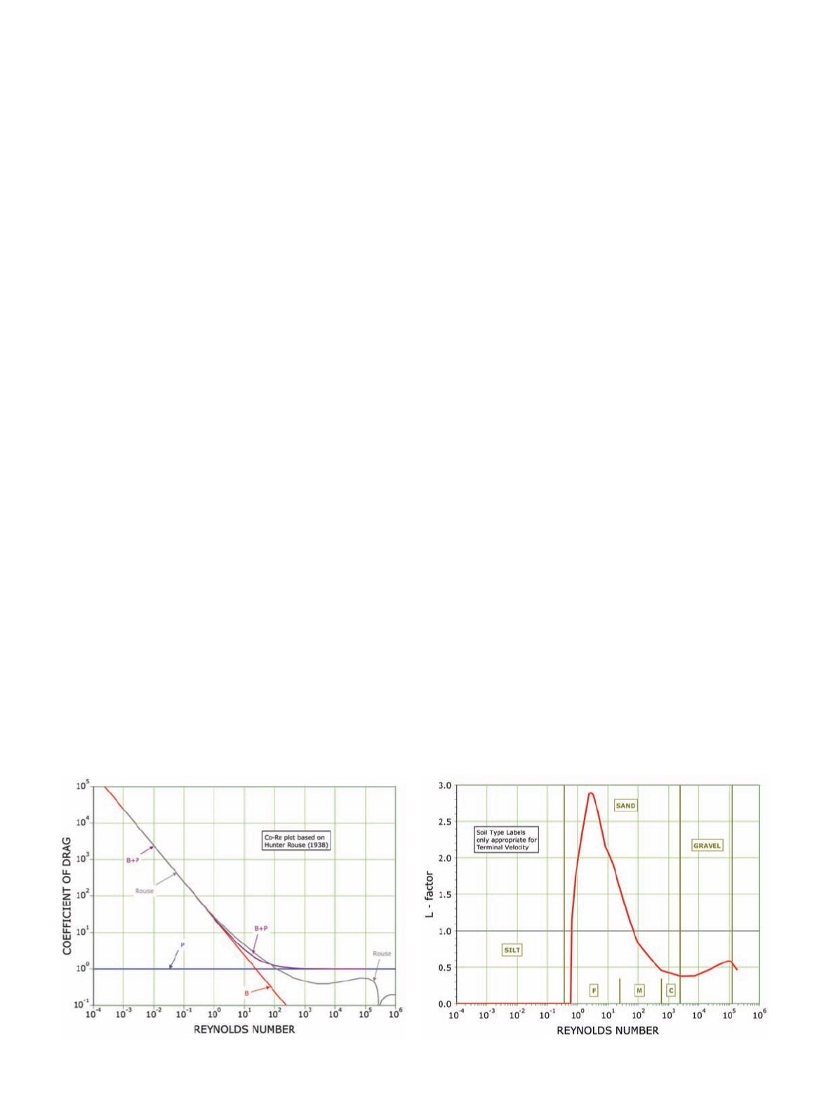
component [F
B
] were the full equiva-
lent of the Drag Force [F
D
] then C
D
would equal 24μ/ρvD. This equivalent
value is plotted as the solid red line
marked “B” on Figure 7.
Standpipe Piezometer
At anypointwhereflowinggroundwater
is locally blocked, and made to become
stationary, the kinetic energy of the
water is transformed into hydraulic
pressure. The energy conversion from
dynamic to static is given by:
h = v
2
/ 2 g
where “h” is the pressure head in metres
of water. It represents the additional
amount by which the water level in a
standpipe piezometer will be increased
by being placed within flowing water,
as opposed to stationary water. This is
because the water level in the standpipe,
being static and balanced, must equal
the energy level of the flowing water to
which it is exposed. The incremental
water pressure associated with this
condition is obtained by multiplying
the head by the unit weight of water [γ
w
= ρ g].
Similarly to what I did above with
the Bearing component I now want to
consider that the Drag Force, or some
fraction of it which I’ll call the Pres-
sure component [F
P
], is equal to that
part of piezometric pressure derived
from the velocity head, so that:
F
P
= ( γ
w
h ) A =
(ρ g v
2
/ 2 g ) A = (ρ v
2
/2 ) A
If this component [F
P
] were the full
equivalent of the Drag Force [F
D
] then
C
D
would equal 1. That is why the blue
line marked “P” on Figure 7 is plotted
horizontally through unity.
A new term: the L–factor
As noted above, the grey line in Figure
7 is the relationship between C
D
and R
e
determined by Hunter Rouse back in
1938. What I want to do now is show
that this unfamiliar parameter C
D
can
be replaced with a simple combination
of the two geotechnical pressure terms:
γ
w
h, and q
ult
.
What we can see/learn from the red
line marked “B” on Figure 7 is that set-
ting C
D
equal to 24μ/ρvD, the value
from which F
B
is derived, this swap
provides an exact replication of C
D
for
any value above about 30 or 40; but
thereafter, it is an inaccurate underes-
timation. This means that replacing the
original Drag Force F
D
by the Bearing
Figure 7. The coefficient of drag.
Figure 8. The L-factor.


